Featured Post

Beolover SyncDrive: DC Platter Motor Replacement for Beogram 4002 and 4004 (Type 551x and 552x)

Late Beogram 4002 and the 4004 (Types 551x and 552x), which have DC platter motors instead of the earlier synchronous AC motors usually suff...

Showing posts with label sn1182050. Show all posts

Monday, April 11, 2022

Beomaster 2000 Type 2801: Finishing things up

In the last post I was pretty pleased with my new lamp socket for the Beomaster 2000 dial pointer.  It was going to be great. 

Unfortunately the joy was short lived.

As I examined the inside of the Beomaster cabinet to test fit the new dial pointer assembly I discovered that the nice lamp socket requires a depth of about 7 mm more than is available.

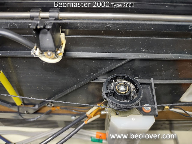
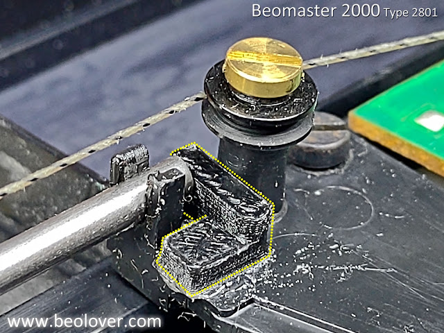
This photo shows the path that the dial pointer must travel which takes it over the top of a number of adjustable tuning inductors. 

The nice, new assembly doesn't fit.


So it was on to Plan B.
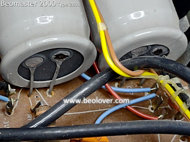
I removed the lamp socket and returned to soldering the leads of the wedge style lamp to the power wires.  It isn't as pretty but it is how it has to be.


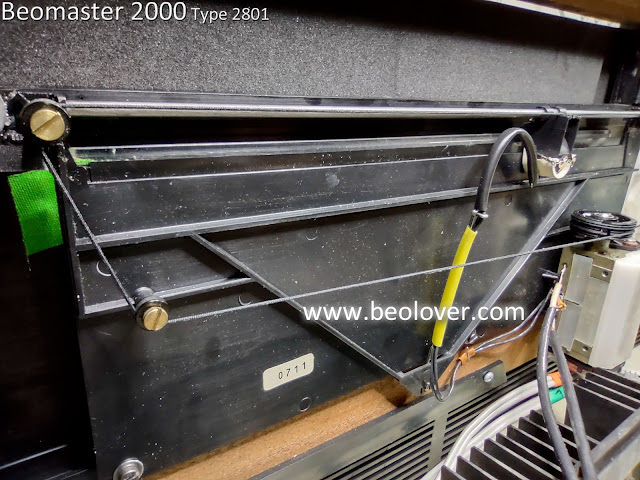
Now there is room for the dial pointer to navigate across the tuning dial.

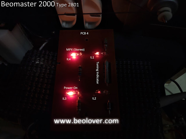
In testing the Beomaster 2000 lamps I noticed there is a bit of bleeding of the power on and stereo lamps over to the tuning balance lamp window.

I decided to cut a thin piece of black, heavy-duty tape to mask off the two lamp holders.


Now I could properly install the dial pointer and lamp board in their final positions.


After calibrating the dial pointer on the dial cord I rechecked the tuning voltages again per the service manual. 

Before closing up the cabinet I had one more repair to make.
I had noticed that the rear DIN jack for Tape 1 was loose.
As I have seen on other Beomaster types with similar style DIN jacks, this one had broken tabs that hold the DIN jack in place in the cabinet frame.


I used some parts I had from a Beolover DIN jack repair kit for the Beomaster 8000.
The side pieces fit perfectly on this DIN jack to secure (with a little glue) the DIN jack in place.


They work great and are so much more pleasing than globs of epoxy I have seen on other repair attempts.

Here, finally, is the reassembled Beomaster 2000 Type 2801 receiver playing music again.


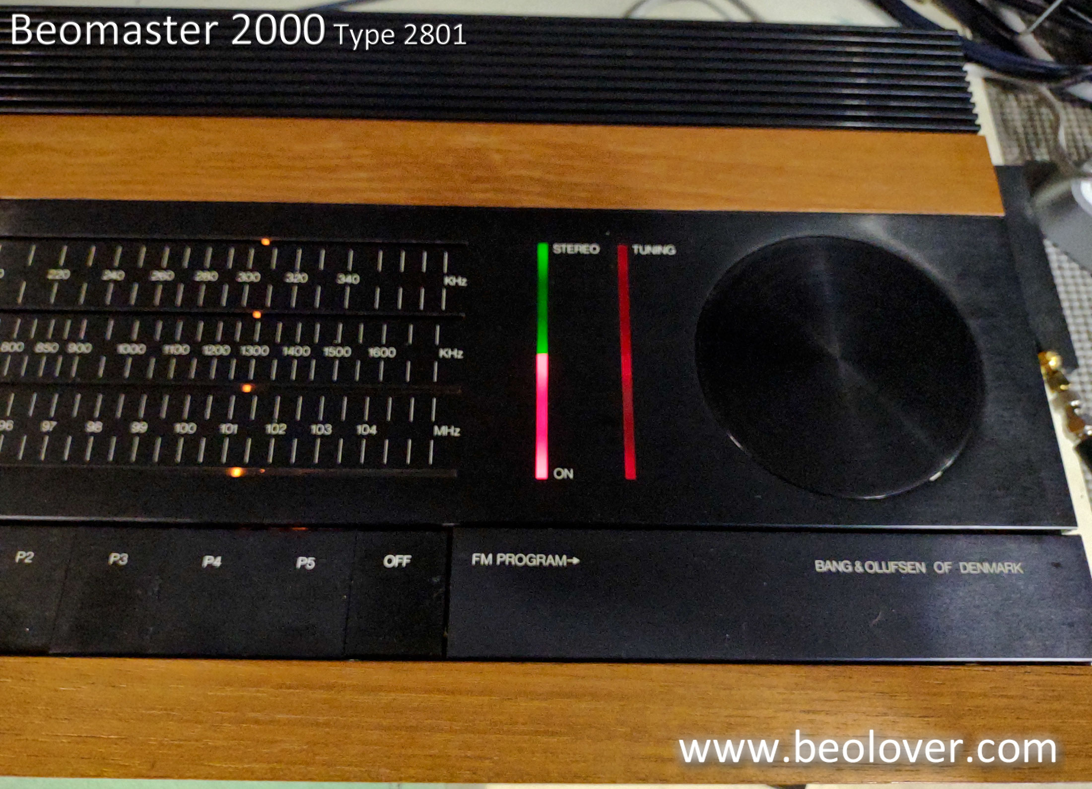
So far I have only listened to the FM, AM, Tape 1 and Tape 2 source inputs.  The sound is very nice.  I am currently using a pair of Beovox S-55 speakers in my workshop to listen with.
It is different from the Beomaster 4400 for sure but I can't really describe it.  There isn't anything negative I can say about it so I will move this Beomaster to a listening room where I can properly connect up a Beogram and a Beocord.

...But first a quick check on the QuantAsylum QA401 Audio Analyzer that I always check out my amplifiers with.

The speaker outputs are connected to a pair of fixed 8Ω dummy loads.
The QA401 is set to send a 316mVrms, 1KHz sine wave into the Beomaster Tape 1 input.
I will adjust the volume on the Beomaster 2000 to achieve the maximum output I can get without badly distorting the output.

With this Beomaster 2000 that maximum output power turned out to be about 25 Watts.
That was slightly surprising as other Beomaster amplifiers have always reached their stated power outputs.  The expected output level for this Beomaster 2000 is 30 Watts across 8 Ω with a THD of less than 0.1% for a 1Khz sine wave input.

My measurement gave me 25 Watts across 8 Ω with a THD of 0.03% (so very nice there).
Above 25 Watts however, things diminish rather quickly.

The frequency response measurement at 25 Watts was also respectable.  The left and right channel outputs across the 20 Hz to 20,0000 Hz range varied by less than the ±1.5dB specification.


In my listening test in the workshop I turned played music at a very loud listening level without hearing any noticeable distortion.  So I will move on to some real listening room tests and see how this receiver works in a more enjoyable environment.  

I will save these measurements to compare to the next Beomaster 2000 Type 2801 that comes my way.

Friday, April 8, 2022

Beomaster 2000 Type 2801: Installing the new dial pointer

The Beomaster 2000 Type 2801 restoration project left off waiting for a new dial pointer.
The original dial pointer was broken so I had to find a replacement.  Fortunately for me Martin of Beoparts happened to have a spare.

Here is what the back of the original dial pointer looked like where the dial pointer lamp attaches.
The wedge base type lamp appears to have the glass wedge part broken off and the leads wrapped around some plastic tabs of the holder, then soldered to the wires that supply power.
The cavity where the lamp is installed is filled with some sort of glue.


The replacement dial pointer is similar but does not have glue inside where the lamp fits.
The installation for a lamp in this assembly is to unbend the wires on the lamp wedge base and solder them to the two power leads.

I didn't really like that method so I started my lamp installation by first soldering two extension wires (the blue wires in the photo below) on the the power leads.


My plan is to next, install a lamp mount/holder that I "borrowed" from a Beomaster 4400 spare parts unit.  The lamp holder from the Beomaster 4400 has contacts for a wedge base style lamp to plug into.
It also has a small slot under the lamp slot for a mounting tab to slide into.  Hopefully I can figure out a modification to use it.

With a lamp holder any future lamp changes for the dial point will not require any soldering.


Here is the new 12V, wedge base style lamp in the lamp holder...ready to be inserted into the dial pointer frame.


Here is the lamp assembly installed into the dial pointer.  For now I will not secure it and leave it loose while I figure out how to add a mounting tab to the assembly.  I hope to avoid having to secure the lamp assembly with glue the way the original was mounted.  The mounting tab like the Beomaster 4400 uses is much cleaner.


...and here is the Beomaster 2000 turned on with the new, illuminated dial pointer.


Saturday, February 19, 2022

Beomaster 2000 Type 2801: Finishing up the FM Tuning Balance and FM Muting adjustments

This Beomaster 2000 has been playing great on the workbench. 


In the last post I had made adjustments on the PCB 2 board with the FM Detect trimmer (2R28), the FM Tuning Indicator trimmer (2R31) and the FM Level trimmer (2R11).

The sound was good and the performance of the audio muting for FM, Phono and Tape sources was working.

There was an issue, however, with one of the FM tuning indicator lamps remaining on when a Phono or Tape source button was engaged.  

Before making any more adjustments I decided to replace a couple more trimmers and check some more capacitors that are in the related circuit.  

The capacitors checked out fine and I replaced trimmer 2R11 (FM Level) and 2R63 (+26V Reference Voltage).  After that bit of work I set up my measurement probes to measure and re-adjust the trimmers involved with the FM tuning indicator lamps and the FM muting circuit.

Since I changed the 2R63 trimmer that controls the reference +26V I readjusted it first as it is used in the circuits I am working on.

Here is a look at the work area with all of the measurement probes attached.


After the +26V reference was set to 26.00 VDC I went through the FM signal balance and signal muting test points again.

When I powered on for the first time since adding a new 2R11 (FM Level) trimmer I discovered that the audio muting circuit was enabled when I selected Tape as the music source.  I also saw that one of the two Tuning Indicator lamps was illuminated.

That makes sense to me now since a new 2R11, FM Level trimmer was installed and had not been adjusted yet.

I turned the 2R11 trimmer counter-clockwise until the tuning indicator lamp went out and the audio muting turned off (and I could hear music via the Tape source).

The next step was to go through the adjustment and measuring iteration of the FM Detect Balance and FM Tuning Indicator Balance again.  I used the same method as before where I monitored the FM Muting signal and the two indicator lamps as I adjusted 2R28 and 2R31.

The goal in the adjustment is to have a strong FM signal dialed in perfectly listening to the results by ear.  When I determined an FM station was tuned as good as possible I made any adjustment up or down on the trimmers so the lamps (IL1 & IL2) were identically illuminated.  I also had to recheck that neither IL1 or IL2 were illuminating when the Tape source is selected.

Being familiar with the procedure now it didn't take long to get the tuning balance and muting adjusted where I liked it.  Here are the lamps with a good FM station tuned in.


The next two pictures show the tuning balance indicator lamps when they are away from center position for the FM station being tuned.


Here are is the display when Phono or Tape are selected as the audio source.


I decided it would be a good idea to note the signal values I measured on the schematic to have as a reference guide the next time I restore a Beomaster 2000 (Type 2801).

The marked up schematic here shows the original service manual FM muting circuit along with the re-drawn circuit per the actual muting circuit on this Beomaster.

On the circuit I show the DC voltage values I measured when a Tape source is selected, a tuned in FM source is selected and an FM source with no station present is selected.  The last scenario is when the FM muting circuit activates while the first two conditions result in no audio muting.


The FM reception is very good and the Tape source is working perfectly.
Overall I am happy with the adjustments.

I will leave this Beomaster 2000 unit to sit and play music for a while as I wait for the replacement dial pointer to arrive from Denmark.


Thursday, February 17, 2022

Beomaster 2000 Type 2801: Back to the Beomaster 2000 to repair the dial cord

I left off the last Beolover Blog post on the Beomaster 2000 (Type 2801)  with the key voltages checked and the amplifier working.  The Beomaster display lamps were in need of replacement. Some were burned out.  I also found a badly frayed spot on the tuning dial cord.  Both the lamps and the dial cord were items I didn't have on hand and had to order.

Those are here now and I started in on the replacement.

I decided to tackle the dial cord first.  It seemed the most challenging based on the service manual instructions.


I received a very nice radio dial cord in black from Bob's Antique Radio & Electronics.
The dial cord he supplies is 0.028 inch diameter, non-stretch nylon cord with a fiberglass core.
It is sold in 25 foot length.  I only need 114 centimeters (57 cm when assembled as a loop).  
That is 44 and 7/8 inches.

The old, frayed cord has knots on both ends that connect the spring mechanism that secures the cord to the tuning dial pulley.  Having not restrung a dial cord before I did some research on other radio DIY repairs.  I decided the best way for me to go was to make a replacement cord so that I have a knot on each end that, when stretched, measure 44 7/8 inches (114 cm) from the apex of one knot loop to the other.

The type of knot I selected is what is called a "perfection loop" knot.


There are probably better instructional diagrams for this type of knot but I like this one because it shows the apex where I am making my 114 centimeter measurement from.

Once completed I only had to wind the cord around the dial components per the service manual and slip the end loops over the hook in the spring part (that attaches to a post in the pulley).

Here are some photos of the restrung dial cord.


You may have noticed in the photos that the display board was removed from its location.
That is the next restoration step I worked on.

The display board has four lamps (Power On, FM Stereo, Tuning Balance 1 and Tuning Balance 2).


I removed the old double-sided foam tape and replaced it with some modern 3M double-sided tape.
Here are the new lamps I received from Martin Olsen installed.


There is a fifth lamp that I need to replace.  That is the one on the dial pointer.
Power to all the lamps pass through the dial pointer lamp so it has to be present (and not open circuit) for any of the lamps to function.

This is where I ran into a problem.
It turns out that the dial point assembly on this Beomaster 2000 had seen better days and someone had tried some repair work sometime in its past.

Here is what it looks like removed.


The worst part is that someone glued and taped the assembly together.
It is impossible to replace the lamp inside without breaking into the glued casing.

That was my only option.

I was able to salvage the pieces in such a way that I have a pretty good chance of rebuilding a dial pointer assembly from them.


Fortunately I checked with Martin Olsen and he just happened to have a spare Beomaster 2000 (Type 2801) dial pointer assembly.  It is now on its way to me for this project.

In order to continue on with testing the Beomaster 2000 I used a spare lamp holder and connected the replacement dial pointer lamp up so the Beomaster could turn on that the other lamps checked out.


The lamps work now :-).  
The one that is not illuminated works when a station is properly tuned in.

However, the fact that it isn't illuminated in the picture here represented another problem I ran into.

I couldn't tune in any FM stations. When I tried I would hear a very short burst of sound from a station but then it would go dead.  Attempting the station tuning with the muting switch disengaged would allow me to hear faint stations (and no stereo) but as soon as I dialed them in better the sound would go dead.

This problem lead me to monitoring the FM mute signal.
Sure enough, the mute signal was active (about 22V) when a station was dialed in.
When I switched sources to Tape the mute signal would drop down to about -8.3V.

The Beomaster 2000 has a source muting circuit to mute the preamplifier audio to the output amplifier whenever a source selection is made. In addition, there is an FM muting control signal that ties into the audio mute whenever a station is being tuned.

Interestingly, the Beomaster 2000 has a switch to turn the FM station muting on and off.
In this case that function was not doing anything. I always had a muted FM audio signal.

Here is the schematic of the Beomaster 2000 FM muting.
Note that I show two versions of the schematic. One is from the service manual.  The other is drawn up per the way this Beomaster 2000 unit is actually wired.


The service manual schematic shows 2R40 as a trimmer resistor for adjusting the FM muting circuit.
That looked like a good place to start on this Beomaster FM problem...until I went to adjust it and it wasn't there.  

The circuit diagram on the right is how the PCB 2 board is on this Beomaster unit.
I am guessing that perhaps this Beomaster unit is an early serial number (and version) while the service manual shows an improved circuit.  I don't know for certain yet but you can see that there is no trimming resistor specifically for FM muting on the Beomaster 2000 of this project.

Related to the FM muting circuit are the FM Detect Balance and the Indicator Balance circuits (also shown in the diagram).

Each of those circuits have a trimmer resistor for adjustments.

When I changed those I started getting some FM station tuning results and some movement on the problem FM muting signal.

Here is what the actual PCB 2 looked like in the area that goes with the schematic above.


Trimmers 2R28 and 2R31 didn't look like they were in too good of shape.
I replaced them and when I measured them by themselves they did have some dead spots.
I decided to check the transistors while I was de-soldering components.
2TR6, 2IC2 and 2IC 3 all measured good (out of circuit) so I put them back.
The tantalums I spot checked earlier measured right on so I hadn't check the three involved here (2C20, 2C51 and 2C52). These three are 0.1uF capacitors.  When I de-soldered and checked them here, they measured around 0.07uF. So 30% out of tolerance. 

I replaced the trimmers (2R28 and 2R31) and the three 0.1uF tantalum capacitors.

Here is the board after those changes.
I have an oscilloscope probe attached to the FM muting signal for monitoring (while I adjust trimmers 2R28 and 2R31).


Here is a closer look at the FM muting circuit components on PCB 2.


With these changes I was able to adjust the FM Detect balance and the FM Indicator balance trimmers so a tuned in station displays evenly on the two tuning balance lamps, the FM stereo light functions correctly and the audio muting circuit behaves properly.

There are still some additional checks that I want to make and when I receive the replacement tuning pointer assembly I will have to install that.

I have a question I need to figure out the answer for on the display lamps.
When I switch from an FM source to Phono or Tape the bottom tuning balance lamp (IL2) displays at full illumination to match the Beomaster 2000 Power On lamp.

I don't know if that is proper behavior or not. It seems like neither FM indicator lamp should be illuminated if a Phono or Tape source button is pressed.  The Tape source is working well and FM stereo stations are being tuned in. I haven't found any adjustment for that indicator lamp other than the balance trimmers...and they are currently adjusted so that FM signals are received on both channels evenly.

I will have to track down the signal that is causing the IL2 balance lamp to illuminate when a Tape or Phono source is selected.

Sunday, January 23, 2022

Beomaster 2000 Type 2801: Replacing Some Components and First Music Listening Test

I received most of the electronic components I needed to restore this Beomaster 2000 receiver.
Compared to the last few Beomaster receivers I have restored this one will have the least amount of capacitors replaced.  As I mentioned in the previous blog post ...for this unit I will leave in all of the red tantalum capacitors if a spot check shows them to be good...and it did.

Here is a small sampling of three different tantalum capacitors from the Beomaster 2000.


I didn't remove and test every single tantalum but I tested enough where I was satisfied the plan to leave them in is sound (sorry for the unintended pun :-) ).

I did replace the electrolytic capacitors, the no-load current adjustment trimmers (two...one for the left channel and one for the right channel) and the 2D8 bridge rectifier.

Here is a before and after photo of the 470uF 2C24 capacitor and the 2D8 bridge rectifier (located on PCB 2).

Before:


After:


The output amplifier board (PCB 7) had seven electrolytic capacitors to replace and two 250Ω trimmer resistors for the left and right channel no-load current adjustment.

Before:


After:


Note: The thermal compound on the transistors mounted on the rear heat sink of the Beomaster 2000 cabinet was still soft so I left those alone.  If there ends up being a problem with the transistors and I have to replace any, I will rework all of the output transistors.
For now...they are left as they are.

PCB 5 (IF & Preamplifier) only has two electrolytic capacitors to replace.  Here are the before and after photos for that board.

Before:


After:


That sums up the PCB component replacement tasks.

PCB 3 (Pre-set Tuning board) required desoldering of the five pre-set dials.
The issue with this board was that the black, plastic adjustment knob for each preset was slipping.

I cleaned all of the preset components with some fader lube, glued on the plastic knobs and then reinstalled the five presets to PCB 3.


Next, it was time to check powering up the Beomaster and checking voltages.

I set the voltage selection switch to 130 VAC as here in the USA the line voltage is closer to 130 V than it is to 110 V (the other voltage switch selection option available to me).


On these initial power up tests I use my variac and dim bulb tester to protect any short circuits to ground in the Beomaster power supply path.

As you can see the line voltage is closer to 130 V than 110 V so 130 V is the best selection for my area.


For reference here is the Beomaster 2000 Type 2801 line voltage supply wire routing for the four voltage select options.  Top left is the wiring for my selection.


With the Beomaster turned on (Tape selected) I measured the secondaries off the transformer.
One set should be at 26 V and the other should be 46 V.


Those are good values for the power coming in.

Checking the resulting ±30 VDC rail voltages I measure -


Those measure good.

Now to check the +26 VDC adjustment called for in the Beomaster 2000 service manual.
I monitored the +26V test point and adjusted the trimmer to get as close to 26V as I could.


After that I adjusted the output amplifier no-load current for both channels per the service manual.
The adjustment calls for no speakers connected, the volume level at zero, the amplifier warmed up and a measurement of 10mVDC across emitter resistors (7R119 : LCh, 7R219 : RCh).

Here are those measurements using the new Bourns multi-turn trimmers I installed to adjust the voltages.

Left Channel


Right Channel


Those are all the initial voltage checks I wanted to do.
Now to hook up speakers and see if I have music playing from this receiver.

This picture shows my little iPod Nano providing the music source to the Beomaster 2000 Tape 2 input.
You can also see in the photo that the lamp for the tuner dial is illuminated.


Listening to music from the restored amplifier is a nice milestone to reach in the project.

Normally I would move into some performance testing but there are a few problems to address with this Beomaster first.

There are no lamps lit up on the PCB 4 Indicator circuit.  It has four 12V, 30mA lamps and they appear to be burned out.


I should have checked that earlier but now I will have to wait for those parts to arrive.

When examining the tuner dial cord I discovered another problem.  The cord has a spot that is badly frayed.  I don't want to put in all of this work only to have the cord break later.  I ordered a replacement for that and will also have to wait for that to be delivered.


I also had to repair two of the tuning cord pulley posts because there were defects in the plastic parts.

On the left side of the dial window the plastic mounting tab for the pulley was broken when I initially checked over the Beomaster 2000 inside.


I was able to glue that broken piece back together but the break across the plastic part will see a lot of stress so I don't think it will hold up over time on its own.


For that reason I fashioned a u-channel reinforcement part that I could epoxy into place across the break.


The right side of the dial cord assembly also had a problem.
There appeared to be a missing pieces (a plastic tab) that keeps the metal rod for the dial assembly from pulling out of place.


I fashioned a second 3D part to keep metal rod in place. It too was installed using some epoxy.


That was not the end of the problems for the right side dial cord pulley though.

I could easily see that the pulley assembly was loose and would not remain in place when the tension of the dial cord was pressing on it.

It turns out there were some cracks in the plastic mounting post for that pulley assembly.
So the mounting screw would expand the cracked mounting post when pressure from the dial cord is applied.

For that repair I made a ring for the post so the cracks in the post couldn't expand.

That work out really well.  Satisfied that repair would work I epoxied the ring in place.


This Beomaster should be ready for further testing once the replacement lamps and new dial cord arrive.