Featured Post

Beogram Commander Remote Control: Maybe This is the Final Version!..;-)

This is a follow up to my recent post about the redesigned Beogram Commander remote control board, which now works in both (DC-motor) Beogr...

Tuesday, February 28, 2017

Beomaster 8000: FM & FM Interface Board Rework

The FM & FM Interface board assembly (the two boards connect together) appear to have been at the heart of the post burn-in failure that threw a circuit breaker in AC line powering the Beomaster. Once I had rechecked the power supply and output amplifier boards, I found that the Beomaster power up relays for the ±55 VDC rail voltages would fail to engage due to the Beomaster's fault protection circuitry. Unplugging power from the FM Interface board fixed the problem and I began using a spare FM/FM Interface set of boards for the Beomaster tuner.

My plan was to find the bad parts in the FM boards during the recap process and then re-install them. I discovered several defective transistors and a defective diode. This picture shows a couple of the damaged components on the FM Interface board. Since those components were bad I also replaced the three OpAmps on the FM Interface board.


After repairs were made to this board I re-installed it back into the Beomaster. Upon applying power and first selecting TP1 as the source input, I immediately started hearing a buzz in the speakers. Power was quickly removed as well as the FM board assembly. Something there is still not right. I am lucky nothing got damaged and installing it was not my best idea. This board needs to be wrung out on the bench by itself before testing it again in a Beomaster. 

To move forward with this project I decided to take one of my spare FM assemblies and use it. I selected the FM assembly that was closest in part number to the removed FM assembly.


Like the removed, faulty FM assembly I had replaced the electrolytic and tantalum capacitors plus the three TL072 OpAmps. One difference with this spare is that I used sockets for the OpAmps so I could experiment with different OpAmp types. The installed OpAmps here are OPA2134PA chips. The same kind I used in the Filter & Tone Control board.


To be consistent and to provide peace of mind, I decided to replace the TL072 OpAmps in the preamplifier board I completed earlier. Here is the preamplifier board with the OPA2134PA OpAmps installed.


This completes all but the Beomaster Display and Microcomputer boards. I will tackle the Display board next as it requires the most work in updating the displays modules with SMD LEDs.


Beomaster 8000: Filter & Tone Control Board Rework

The Filter & Tone Control Board for this Beomaster had some problems. The first thing was that it wasn't doing its part in the volume control process. The microcomputer tells the Filter & Tone Control Board what volume level to send to the output amplifier. This was not functioning and full volume level was being used.

That problem turned out to be with the Analog Devices Digitally Controlled Audio Attenuator IC (AD7110). This was unfortunate as it is very hard to find this chip anymore. I had to pull two of these (one for the left channel and one for the right channel) from a spare Filter & Tone Control board. But then that is why we have spare boards.

Here is the circuit for the Beomaster 8000 volume control.


When I put the spare board next the the one I am working on I could immediately see a difference in the boards. The spare board was a later version of the board than the board from this Beomaster (serial number 2251030).


The older serial number Beomaster has extra components.


The Beomaster 8000 service manual has a section in the back that describes this circuit as a spike suppression circuit that was removed on later Beomasters.


Thank you B&O for providing good documentation.
After replacing the AD7110 chips the Beomaster volume control was working again. However, now I had some popping noises in the output when I switched the tone filter (bass & treble) on and off. I'm not talking about the slider controls which will need Deoxit treatment. The noise was happening when the Filter button was pressed.

At first I suspected the AD10/192 analog switch (also very difficult to find) so I swapped that IC with the one from my spare filter board but that didn't fix the problem. The filter circuitry uses three OpAmps that are either TL072 or LF343 type OpAmps. The Filter & Tone Control board has five of these in the signal path so I changed them out with OPA2134PA (TI) OpAmps. The OPA2134PA is a high quality audio OpAmp and is what I keep in stock for replacing older audio OpAmps.

That did the trick. No more noise in the Filter & Tone Control board. Here is a picture of the reworked board. The replaced OpAmps are outlined in the picture.


Of course I ran the Beomaster for a while with the Filter & Tone Control board installed. This time I ran the iPod Nano source through TP1 while I started work on the Beomaster FM boards.


Just three more boards to go.

Sunday, February 26, 2017

Beomaster 8000: Second Burn-in Test Results

I ran this second burn-in test for eight hours playing music with the Beomaster volume level at 4.0. After the eight hours I put it into standby mode for three hours then started playing music again. This time everything went smoothly and the amplifier sections are working great.

So far no hiccups on the power relays or anything else. I checked the temperatures of the heatsink mounted transistors (IC201 - IC206) and the two BF857 transistors on the output amplifier board (TR207 and TR211).

The heatsink mounted components measured around 20°C when no music was playing and about 27°C when playing music. The TR207 and TR211 transistors measured around 40°C at idle and around 50°C when playing music.


That should conclude the work on the power supply, output amplifier boards and preamplifier board work. Currently the Beomaster is operating with substitute Filter & Tone Control and FM tuner boards. Those were components that were next in line for restoration so now I have the repair task to add to that. While I work on the remaining boards to restore I can continue running the Beomaster so it gets more burn in time. It is also nice to listen to while I work on the FM boards and the Filter & Tone Control board.

Beomaster 8000: Update On Burn-in Retest

In my previous post I was reinstalling the output amplifier boards into the Beomaster and planning on a retest of the burn-in test.  I was expecting to power on the Beomaster and start playing music again. I should say hoping. I did consider that I still didn't know what caused the circuit breaker trip when powering on the Beomaster after the first burn-in test and that there was likely still a problem lurking.

When I powered the Beomaster up for this second burn-in test I immediately ran into a couple of problems. I didn't actually know right away that there was more than one problem but the first one was the Beomaster ±55 VDC rail relay would not stay engaged. I also noticed that the clipping lamp flashed when I tried turning on the Beomaster.

To find the cause of the power on problem I started disconnecting board connectors and discovered that removing the cables from the power supply to the FM Interface board allowed the rail power relays to start working again. To verify that was the problem I swapped in a spare Beomaster 8000 FM & FM Interface board set and the Beomaster was able to turn on again.

Feeling that I was now ready to begin the burn-in test again I decided to check the output amplifier DC offset voltages again. All of the rework I did on them involved checking the no-load idle current adjustment but I hadn't messed with the DC offset until I now had the boards back in the Beomaster.
I discovered that I couldn't adjust the DC offset in either channel now. So another problem to trace down.

I connected an oscilloscope to the speaker output jacks to see what the output signal looked like. The voltage with no music source playing was around 400mV.  I started playing some music via an iPod Nano connected to the Beomaster TP2 and saw that the output signal from the amplifier board was at a high level even though I had the Beomaster volume dial set to zero. That meant the Beomaster was not controlling its volume output.

The most likely suspect was the Filter & Tone Control board because the preamplifier routes the selected music source up through the Filter & Tone Control board for bass, treble and volume control.


I can't tell what integrated circuit is bad on the board by inspection so I will have to swap out some components to figure it out. It is possible that IC201 and/or IC202 failed as they control the voltage. That will be unfortunate as those are no longer made.

In the meantime I am able to test this suspected board by swapping in one of my spares. Sure enough, with a different Filter & Tone Control board the Beomaster DC output levels could be adjusted on the output amplifiers again and the volume control function works.

I now need to determine what the specific failures are on the FM Interface board and the Filter & Tone Control board. Should the volume control failure be due to IC201 and/or IC202 I can see if Beolover has any spares or I can use the chips from my spare Filter & Tone Control boards. But then I will need replacement AD7110 chips for those.

The good news is I can retest the burn-in test of the power supply, output amplifier and preamplifier again. This test is needed to make sure that initial burn-in test failure is fixed.
Here is the burn-in retest after an hour running. I will leave the Beomaster playing from the iPod Nano overnight and check it in the morning.


Monday, February 20, 2017

Beomaster 8000: Left Channel Output Amplifier Rework Complete

I finished reworking and retesting the Beomaster 8000 left channel output amplifier last night.
Here is everything ready to begin the reassembly. There was the matter of replacing the TR208 transistor that had the cracked case. Luckily I found a spare BD165S transistor.


This time, from lessons learned on the right channel reassembly, I am starting the reinstall of the components to the heatsink from the bottom up. Here is the sequence.


After that was IC205, IC206 then the left row of components also from the bottom up.


From there is was back to the bench test to check out the board and re-adjust the no-load idle current.


Everything tests out good so now I will re-install the board into the Beomaster and re-run the burn-in test. Unfortunately the left side of the Beomaster makes it too difficult to install the output amplifier assembly all connected up. At least I haven't figured out a way to do it. So I will have to un-solder the heatsink assembly wires from the board, then re-solder them once I get the heatsink remounted to the chassis.

Sunday, February 19, 2017

Beomaster 8000: Power Startup Circuit

Since the post burn-in test failure I have reworked the right and left channel output amplifier boards and while I found I needed to update the heatsink component mounting, I didn't find any faults on those boards. That left me with the power start up circuit. That circuit has two relays that control the ±55 VDC rail voltages. The startup circuit worked during the output amplifier burn-in test but failed right after the test. Initially I observed some intermittent power problems where only one of the relays on the startup circuit would energize (RL2). RL1 would not energize and it is the relay controlled by the delay circuit on the power supply board. The RL1 problem finally settled where it never energized.


I spent some time checking components (relay RL1, its D1 diode and the power supply board). As I removed components for this part of the circuit to measure I found the problem underneath the capacitor C21 (22uF, 63V). This was an electrolytic capacitor I recapped at the beginning of the restoration. C21 charges up to 25VDC when the Beomaster turns on (goes from Standby to some play function).  That should result in a short delay between RL2 clicking on and RL1 clicking on.  When I measured the voltage across C21 I wasn't getting anything. When I removed C21 from the board to check it again I saw that the solder pad on the positive terminal was now gone.


I repaired the connection here by running a short jumper from the C21 positive terminal to the D21 cathode terminal.


That fixed the problem with the RL2 relay not engaging when the Beomaster turns on.  Now I have to put the Beomaster boards I removed for this trouble-shooting exercise back in and get back where I can re-run the burn-in test. That is necessary to make sure the original, post burn-in test problem is fixed.

Saturday, February 18, 2017

Beomaster 8000: Left Channel Output Amplifier Heatsink Components Rework

I started looking at the Beomaster startup circuit relays but the left channel output amplifier assembly was on my mind. I just reworked the right channel output amplifier heatsink components and had found the TR208 transistor loose. Several of the TIP141/146 transistors had mica insulators that weren't in very good shape.

The restoration of the right channel looked pretty good to me so I really wanted to do the left channel even though it appeared to be working fine. This is a restoration project so I pulled the left channel amplifier assembly.

I am glad I did. The left channel TR208 had shifted badly. It was also cracked. The mounting screw that was on TR208 is not the correct one. It is the one that should have been used for the R251 (PTC) mount. The tapered head of the screw looks like it put too much pressure on the TR208 case and cracked it.

Somehow TR208 is still working. I measured it anyway and sure enough, it is still alive. However, I am going to replace it with the TR208 transistor from one of my spare output boards.


I am going to wait until tomorrow to finish the left channel output amplifier rework detour. I need to be well rested before taking on the rework of those TIP 141/146 transistors on the heatsink.

Friday, February 17, 2017

Beomaster 8000: Right Channel Output Board Re-checked

I spent the last few days checking the right channel output board components as well as setting up my test bench to do an isolated test of the board.

With the right channel output board assembly completely removed from the Beomaster chassis I de-soldered the connections from the board to the power transistors. This allowed me to measure them with a transistor tester.


I won't show all of the measurements but I ended up checking all of the transistors and diodes on the board. Every component measured good in their out of circuit state. That being the case, I went ahead while the board was out to recheck capacitors. Again, everything measured fine.

Satisfied that none of the components had a hard failure I decided it was time to reinstall them.

Here are the heatsink components ready to be reinstalled. I cleaned off all of the old compound.


After studying the assembly to determine the best way to re-install them I decided I must do it while everything is outside the chassis. It would be really difficult to try and mount the components on the mica insulators and try to get the metal clips in place when there is heatsink compound involved.

The order I decided to go with was to install the middle transistor (IC205) first.


That wasn't too bad. The center transistor is tightly installed and now anchors the wiring harness so the remaining transistors will be easier.
The next transistor I installed was the top transistor (IC204).


That was followed by the small TR208 (BD165).


When I got to the bottom TIP146 (IC206), I realized I would end up having to install it upside down from its original installation in order to easily slide the mounting clip in place. I didn't want to do that
so the bottom transistor (IC204) was a little more difficult to get in than it should have been. The easier way to install these would have been to begin with the bottom transistor (IC204) and work my way up to IC206.

The left side installation (TIP141 transistors) is similar to the right. Here is everything reinstalled and cleaned up.


Here is a better picture of the reworked heatsink mounted components.


I want to retest this board outside of the Beomaster before re-installing it. By using bench power supplies to power the output board I don't have to worry about the rest of the Beomaster and should be able to find out for sure if the problem is on this board.

I had to wait for the arrival of two new 60 VDC adjustable bench power supplies to do this test as the output board rail voltages are ±55 V.  My existing 30 VDC bench power supply can provide the +15 VDC needed. Fortunately the new supplies arrived this week.

Here is the test setup. I created special test wires with connector plugs to attach the power and grounds to the board.


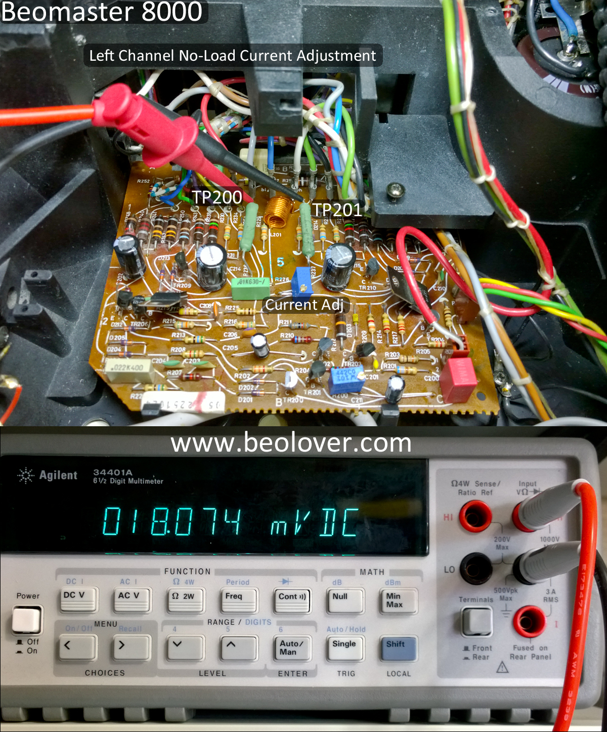
The power and grounds are marked on the picture and those lines go to the bench power supplies. The two mini-grabber probes are from the DVM to check the no-load idle current.
Here are the bench supplies after slowly ramping up their ±55 VDC rail voltages. That was followed by ramping up the +15 VDC voltage.


When I got the ±55 V supplies ramped up to their levels and the +15 ramped up to its level, I adjusted the no-load idle current to an initial value of 18mV. That resulted in about 0.11 amp current on each 60V supply which is what the expected value is.  Leaving the output board powered up I left it on for a while and the no-load idle current measurement (TP200 to TP201) crept up to about 22mV and settled there.


This is good news as it appears this output amplifier assembly is good. I will reinstall it in the Beomaster and re-run the burn-in test to see if the earlier fault appears again. That still concerns me as I haven't found a problem related to that yet. In performing my re-check of the output board components I pretty much re-flowed solder on all of the board.

Here is the right channel output board re-install. It can fit in through the back without having to remove the heatsink harness from the board. That is a relief.


Wired back up.


The power test reveals there is still a problem but it has more clarity now.


The Beomaster powers up into the Standby mode as it should. When I press a source function (TP2 in this case) the display shows the selected source at the saved volume level.

A missing key event is happening now. There is no delayed, second relay click for the ±55 V rail supplies to kick in. So the Beomaster is showing On but the output amplifier is not powered.

A few days ago, before I removed and checked the right channel output board, I ran tests where I had removed the rail voltage connections from the Beomaster output boards. When I ran the same power on tests the ±55V rail voltages would usually come on (the second relay would engage). However, occasionally the relay would not engage.

Tomorrow I will have to trouble-shoot the start up circuit in the back and see if there is a problem with the power relay.

Monday, February 13, 2017

Beomaster 8000: Unexpected Burn-in Test Results

I successfully played music through the Beomaster for about eight hours. That felt like a good test and I put the Beomaster into Standby mode.

The next morning I wanted to check the Beomaster again. When I switched the Beomaster on (from Standby to TP2) the house circuit breaker for the outlet I was using tripped. What a surprise. Not wanting to take any chances I plugged the Beomaster into my dim bulb tester, reset the house circuit breaker and turned the receiver on again. Now it would try to switch on but immediately go back to Standby.

So trouble-shooting this power problem became the order of the day. This is why burn-in testing is necessary.

I suspected something with the output amplifiers so I unplugged the rail voltages. The Beomaster would now switch on and the ±55 VDC rail voltages measured okay (when not connected to the output amplifier boards). I will note that I also had to take the Beomaster off the dim bulb tester at this point because it interfered with the power up.

After some more trouble-shooting I determined that the left channel output amplifier board appears to be good. I was able to hook the left channel rail voltages back up and check the no-load idle current and DC offset. This was not the case for the right channel output amplifier. I re-connected the right channel rail voltages again and they measure correctly when the Beomaster turns on  However, there is no right channel output. The no-load idle current stays zero volts.

The problem is in the right channel output amplifier so I will need to examine that whole assembly.
Here is the right channel output amplifier assembly removed from the Beomaster chassis.


Here is the output amplifier with the components removed from the heatsink -


I discovered that TR208 (NPN) was not securely fastened to the heatsink. The mounting screw was loose and it was free to move. That doesn't mean it is the culprit but I probably need to make removing and checking this assembly part of my normal Beomaster 8000 restoration process.

The next step is to check the transistors and diodes of this circuit to see if there are any failed components.

Friday, February 10, 2017

Beomaster 8000: Stop and smell the roses day

With the Beomaster power supply, output amplifier and preamplifier boards restoration tasks complete it is time to see what this receiver can do before continuing on.

I moved the Beomaster to my test bench and began measuring the voltages from the power supply.
Starting with the ±15 VDC regulators and the 5 VDC regulator, everything testing out good.
Here are pictures of those measurements.


The next check was the ±55 VDC voltage rails for the left and right channel output amplifiers. Those also measured good.


This is a nice milestone for the project to have the Beomaster 8000 powered on and the voltages all verified. Now it is time to adjust the no-load idle current and DC offset voltage of the left and right channel output amplifiers. This is a must do. Especially before connecting up any speakers.

The service manual describes the No-Load Current Adjustment here -


The method I use is option 1 - To measure 18mVDC across TP200 and TP201. The 18mVDC measurement is to be made right as the Beomaster is powered on (before it is fully warmed up).
Here is a picture of the left channel adjustment (the right channel board is identical).


After the no-load current adjustment the service manual shows the DC offset adjustment.


This is also an easy adjustment to hook up for. I attach my DVM leads to the Speaker 1 terminals and turn on the Speaker 1 switch (no speakers are connected at this point though).
The other Bourns trimmer I installed is the one that controls this adjustment. It can be seen in the lower left of the picture.


After the Beomaster was left on for a while I re-adjusted the left and right DC offset again to as low as I could get it.


Now for a real world test. I connected up a pair of Beovox S55 speakers I keep in my workshop and connected an FM antenna to the Beomaster.
It has sound -


The next part of the test drive I turned on the filters (bass & treble) for the Beomaster and connected an iPod Nano to the TP2 input. I also cranked the volume up.


The Beomaster sounds great. This is such a favorite receiver of mine.
Remember that in my pre-restoration testing of this Beomaster it would only play for a short amount of time before stopping. So far I have been playing music through this receiver for over an hour without a hiccup. It would appear the problem it was having was related to power.

I will leave the Beomaster playing for a few more hours to make sure. After that it will be time to move on to the last few boards for recapping, replacing the old displays with SMD LED devices and finding a damper for the control panel lid. Then this Beomaster will be ready to be returned to its owner.