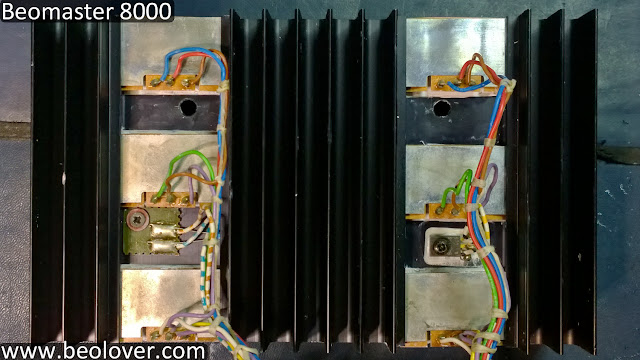
With the right channel output board assembly completely removed from the Beomaster chassis I de-soldered the connections from the board to the power transistors. This allowed me to measure them with a transistor tester.
I won't show all of the measurements but I ended up checking all of the transistors and diodes on the board. Every component measured good in their out of circuit state. That being the case, I went ahead while the board was out to recheck capacitors. Again, everything measured fine.
Satisfied that none of the components had a hard failure I decided it was time to reinstall them.
Here are the heatsink components ready to be reinstalled. I cleaned off all of the old compound.
After studying the assembly to determine the best way to re-install them I decided I must do it while everything is outside the chassis. It would be really difficult to try and mount the components on the mica insulators and try to get the metal clips in place when there is heatsink compound involved.
The order I decided to go with was to install the middle transistor (IC205) first.
That wasn't too bad. The center transistor is tightly installed and now anchors the wiring harness so the remaining transistors will be easier.
The next transistor I installed was the top transistor (IC204).
That was followed by the small TR208 (BD165).
When I got to the bottom TIP146 (IC206), I realized I would end up having to install it upside down from its original installation in order to easily slide the mounting clip in place. I didn't want to do that
so the bottom transistor (IC204) was a little more difficult to get in than it should have been. The easier way to install these would have been to begin with the bottom transistor (IC204) and work my way up to IC206.
The left side installation (TIP141 transistors) is similar to the right. Here is everything reinstalled and cleaned up.
Here is a better picture of the reworked heatsink mounted components.
I want to retest this board outside of the Beomaster before re-installing it. By using bench power supplies to power the output board I don't have to worry about the rest of the Beomaster and should be able to find out for sure if the problem is on this board.
I had to wait for the arrival of two new 60 VDC adjustable bench power supplies to do this test as the output board rail voltages are ±55 V. My existing 30 VDC bench power supply can provide the +15 VDC needed. Fortunately the new supplies arrived this week.
Here is the test setup. I created special test wires with connector plugs to attach the power and grounds to the board.
The power and grounds are marked on the picture and those lines go to the bench power supplies. The two mini-grabber probes are from the DVM to check the no-load idle current.
Here are the bench supplies after slowly ramping up their ±55 VDC rail voltages. That was followed by ramping up the +15 VDC voltage.
When I got the ±55 V supplies ramped up to their levels and the +15 ramped up to its level, I adjusted the no-load idle current to an initial value of 18mV. That resulted in about 0.11 amp current on each 60V supply which is what the expected value is. Leaving the output board powered up I left it on for a while and the no-load idle current measurement (TP200 to TP201) crept up to about 22mV and settled there.
This is good news as it appears this output amplifier assembly is good. I will reinstall it in the Beomaster and re-run the burn-in test to see if the earlier fault appears again. That still concerns me as I haven't found a problem related to that yet. In performing my re-check of the output board components I pretty much re-flowed solder on all of the board.
Here is the right channel output board re-install. It can fit in through the back without having to remove the heatsink harness from the board. That is a relief.
Wired back up.
The power test reveals there is still a problem but it has more clarity now.
The Beomaster powers up into the Standby mode as it should. When I press a source function (TP2 in this case) the display shows the selected source at the saved volume level.
A missing key event is happening now. There is no delayed, second relay click for the ±55 V rail supplies to kick in. So the Beomaster is showing On but the output amplifier is not powered.
A few days ago, before I removed and checked the right channel output board, I ran tests where I had removed the rail voltage connections from the Beomaster output boards. When I ran the same power on tests the ±55V rail voltages would usually come on (the second relay would engage). However, occasionally the relay would not engage.
Tomorrow I will have to trouble-shoot the start up circuit in the back and see if there is a problem with the power relay.


No comments:
Post a Comment
Comments and suggestions are welcome!