Another task to do on this board while it is removed is to re-flow the solder joints on all of the board connectors and the pots (that I cleaned with Deoxit). This will insure that there isn't some hidden cold solder joint lurking in those board connector joints.
Here is the Beomaster 8000 preamplifier board as removed from the chassis.
Here is the board with the capacitors removed, the input source volume pots cleaned and the solder joints re-flowed. Ten of the electrolytic capacitors on this board are in the signal path and are 10uF, 63V. There are also a couple of 100uF capacitors and two 10uF tantalums. Several of the 10uF electrolytics were on the upper end of their tolerance limits and a few were over.
As I started to replace the electrolytic capacitors on this preamplifier board something jogged my memory regarding the C130 (10uF, 63V) capacitor.
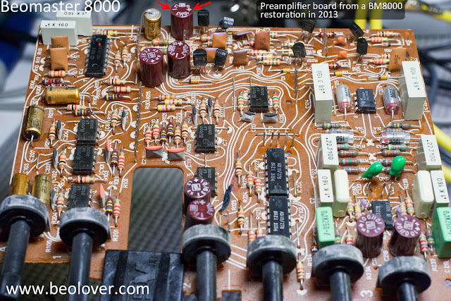
Here is the picture of the preamplifier board before removing the capacitors again. The C130 capacitor is highlighted by the red arrows.
What jogged my memory was looking at the photo again and seeing the polarity of the installed C130 capacitor. Look at Beolover's original Beomaster 8000 restoration picture on this blog page. If you zoom in to his before and after recap pictures you can see that the C130 capacitor is installed with the opposite polarity of this one. I remembered something about this particular capacitor on my own Beomaster 8000 restoration in 2013. Here is the preamplifier board of that Beomaster before the recap. It has the polarity the same as the preamplifier board I am working on.
However, you can see on the recapped 2013 Beomaster preamplifier that my replacement C130 put the capacitor in with the same polarity as Beolover's preamplifier board. Here is a picture of my 2013 board after my recap.
I checked the Beomaster 8000 schematic for the preamplifier board and it does show that the polarity for C130 and C230 does go with the negative side towards the base of NPN transistor (TR101 & TR201 respectively).
So the preamplifier board prior to the recap on my 2013 Beomaster had been installed incorrectly.
I always assumed someone worked on it and put the capacitor in backwards. The odd thing is the C130 capacitor looked like it was the original capacitor so why would it have been removed and reversed?
Now, on this 2017 Beomaster project, I come across another preamplifier board with C130 also installed backwards...and it appears to be original. Could this have been a mistake on the assembly line? I guess the voltage across it is always low enough that the electrolytic capacitor was able to handle being installed with its polarity reversed.
UPDATE NOTE: It turns out that for this coupling capacitor application the polarity is not really important. During operation the small, preamplifier audio signal will be constantly changing so the coupling capacitor is always changing states. When no audio signal is present it is likely the DC voltage is pretty near 0 volts. I will be interested to measure it when I power this Beomaster up.
With the puzzling capacitor polarity figured out, I installed the new C130 10uF, 63V capacitor into the preamplifier board per the schematic (just to be consistent). Here is the recapped preamplifier board for this project.
This board is ready for re-installation in the Beomaster.
...and here the Beomaster is with everything reconnected so I can finally test the work done so far (on the power supply, preamplifier and output amplifier boards). I will move the Beomaster to the test bench and see how it looks tomorrow.


Hi, Any conclusions? I am at this juncture too. and why is C130 (C230)?
ReplyDeleteOk - i see the C130 (C230) differences. In the manual
Delete