Featured Post

Beolover SyncDrive: DC Platter Motor Replacement for Beogram 4002 and 4004 (Type 551x and 552x)

Late Beogram 4002 and the 4004 (Types 551x and 552x), which have DC platter motors instead of the earlier synchronous AC motors usually suff...

Saturday, May 28, 2022

Beogram 4000: Restoration and Exploration of Photocell Function in Sensor Arm

I am making good progress with the restoration of the Beogram 4000 that I recently put on my bench. While it seemed on first contact that this unit had escaped 'creative human interaction', I had to learn that it had been worked on by a tinkerer, and that a little bit of a mess had been made of the sensor arm insert that houses the light bulb and the photocell that measures the presence of a record (or rather its absence by detecting the intermittent reflection caused by the black ribs on the platter). My sensor arm LED installation video for Beogram 4002/4 explains in more detail how the circuit works if you are interested. It is pretty much the same circuit in the Beogram 4000.

When I pulled out the sensor arm compartment it immediately became clear that someone had been 'in there' before me: One wire of the photocell was not connected, the other was mangled (from not being careful when pushing the compartment back into the aluminum profile)

and there was some heat damage to the lens insert that focuses both the light emitted towards the platter, as well as the reflected component. This heat damage likely occurred from not being careful with the soldering iron. Amateur hour! Luckily the lenses themselves were not damaged:
I was able to extract the missing wire from the aluminum tube with some narrow tweezers and reconnected it. Then I removed the non-spec light bulb that had been installed (probably disabling the arm lowering circuit due to its non-spec current draw), and I replaced it with a Beolover LED insert (see above video for more details):
Then I adjusted the bias of TR14 to yield 1.8V at the collector 
and installed the adjusted trimmer on the component side that it not interfere with the platter:
Then I measured the sensor response with the oscilloscope and got only a minuscule signal from the ribs passing underneath the sensor of maybe 100mV amplitude. Unfortunately, I forgot to take a picture of the trace. So you gotta believe!...;-). I removed the sensor compartment again, and I had a closer look at the photocell side of the compartment. Usually the photocell is o.k., but here we see that it was not in its correct position (the upside down 'U' in the top rim of the compartment opening). Instead it was hanging down at a ~45 degree angle:
This explained immediately why the signal was so low: The light was not focused on the sensor anymore. I extracted the part:
Then I took the insert to the garage and carefully Dremeled some of the melted mess to make the sensor fit again properly into the aluminum tube:
After checking the sensor by connecting a multimeter in voltage setting to the leads and measuring a promising 0.5V in front of a strong LED lamp, I decided trying installing it to see if it would still work properly. My bench test had revealed that the sensor yielded more voltage on one side than the other (0.4 vs. 0.5V), and so I installed it with the stronger side towards the lens. This resulted in a reversed polarity of the wiring that came about 'naturally' and I did at this point not understand that the polarity matters. The installation of the sensor was done by putting dabs of contact cement in the compartment and on the sensor, and after 10 min drying time carefully pressing the sensor into its slot as shown here:
After soldering the leads I tested the sensor response and I still got a 0.4V signal when shining light onto the lens compartment:
So far so good! The delicate photocell seemed to have been saved, and the need for installing a modern phototransistor averted. But when I tested the sensor signal at the collector of TR14, I saw this signal, which looked inverted compared to the expected trace shape:
It immediately dawned on me that the polarity of the cell matters for this circuit and so I reversed the red and blue wire (I did not want to mess with the cell itself more than necessary)
And tried again. And now the signal looked very good:
A larger than 3V amplitude is excellent and more than enough to guarantee proper record detection. I hope I will soon play a first record on this lovely Beogram 4000!


Friday, May 27, 2022

Beogram 400x: 3D Printed Arm Support for Shipping

I got finally tired of using foam and tape to support the arms of Beogram 400x during shipping. A while ago I received a Beogram for restoration that came packaged with the original B&O arms support made from rubber. Believe it or not: I forgot to take a picture of it! But I copied the design for 3D printing at a later point and then I forgot about it.

Recently, I came across the design and decided to print it with flexible TPU filament. It worked very well:

This is how it installs:
Simply bend the U-cradle a bit apart and slide it under the arms. Then press them gently into the U-shape Done!
No more tape on the arms! This part will become a standard feature of the Beolover shipping container! Beolovely!


Saturday, May 21, 2022

Beogram 4000: MMC Cartridge Mount Restoration

I recently received the tonearm of a Beogram 4000 located in Western Australia. Like in many Beogram 4000s the MMC cartridge mount had broken off.

This Beogram still had the 'old style' tonearm, that elegantly plugs into the base of the arm, instead of featuring soldered signal wiring. However, this makes it more difficult to replace the MMC mount since the insert that goes into the aluminum profile tube has an adapter at the rear that has spring loaded contacts that 'grab' the circuit board that reaches into the back end of the arm to make contact. This shows the sad condition of the MMC mount as received:

The first step of any MMC mount replacement is removal of the broken one. They are usually glued into the arms. Luckily, the glue softens when the arms are 'cooked' for 30 min or so. I heated this one together with the also broken one from a Beogram 4000 from the UK that I am restoring right now:

Replacement of the MMC mount is part of my standard Beogram 4000 restoration package since all mounts seem to be quite brittle at this point in time, and it is an unpleasant event if the broken off tab sticks deep in a cherished $800 rebuilt MMC20CL...This shows the liberated insert after the cooking process:
This is the 3D printed replacement part with installed flex-PCB based contact traces:
The back part with the plug-in contacts mounts onto the thin tab at the end of the part:
This shows the signal wires soldered to the new mount:
And this picture shows all the component put back together. I was able to re-use the bottom part of the mount with the grounding contact for the cartridge housing:
After checking all leads for continuity (sometimes these thin wires can be broken inside the insulation) the next step was inserting the assembly into the arm tube:
I put a bit of white wood glue on the sides of the insert when I push it in to make sure it stays put when cartridges are mounted/pulled off. The defunct cartridge makes sure that the front end components of the assembly are positioned correctly to receive cartridges without any gap between housing and arm tube:
And this shows the final result of the operation:
This tonearm is ready to travel back to Western Australia!


Friday, May 20, 2022

Beogram 4000: A New Arrival From the UK

I recently received a Beogram 4000 from the UK for restoration. It arrived well packaged in a plastic shipping box padded with high density foam. An excellent way to send a Beogram 4000 across 'the big pond'! It arrived in very good condition:

The hood was wrapped in cling wrap and seems to be in very nice condition. The aluminum surfaces are also pretty good:

The plinth came unglued on the right side, but otherwise is in excellent condition with perfect corners:
I removed the panels and platter and had a look:
No 'human interaction' on first glance. Units that were not modified are an excellent starting point for an 'uneventful' functional restoration. There is a bit of corrosion on the leaf springs that hold up the floating chassis:
The fuse box cover has a missing tab:
I will need to think about something to rectify this since it is a safety hazard. The open fuse terminals carry the grid voltage...
Time to fire the unit up for a quick test. First I installed an aluminum pulley to be able to drive the carriage. This unit came without pulley (I may find it later somewhere in the enclosure...they often come off during shipping...;-):
The next step was to exchange the awesome fused UK power plug
with a boring US plug:

Then I switched the unit to 110V and plugged it in. I pressed 'ON' and it came alive. The carriage moved about 10 mm and then stopped, and I was not able to elicit any response from the keypad. Probably corroded switches or a dead 6V rail. On the positive side there is a working strobe light!
And the AC platter motor was running. All the bulbs except 33 RPM (very weak, though) in the keypad seem to be dead, though.
Summarizing, this is a promising unit for restoration to a 'near-new' condition! Usually, functional issues can be repaired in the 4000. It is a pretty sturdy mechanical design and the electronics function without modern microcontrollers. Perfect for an 'extended lifespan'. The next post will be about the restoration of this beauty! Stay tuned.


Friday, May 13, 2022

Beogram 4002: Plexiglass Hood Restoration

The Beogram 4002 (5523) that I restored recently came with a fairly scratched up hood. The good news was that the hinges were not cracked, and that the inside of the hood was almost undamaged. Only a few cleaning 'swirls'. So it was worthwhile trying polishing the hood back to a decent appearance. This shows the hood like it looked when I received the Beogram:

Since some of the scratches could be felt with a fingernail, I started with a 400 grit sand paper and 'equalized' the surface:

This removed all the bigger scratches along with the light ones and turned the hood into a matte, but homogenous surface. This is the usual starting point for polishing it back with ever finer sandpaper. After my usual 7 steps the hood was translucent again and looked pretty decent:

Of course, such polishing efforts are never perfect, and such a hood will never look like a newly moulded one. But this definitely looks much better than the original appearance!

Most 400x hoods have missing rubber bumpers that were supposed to soften the noise when the hood drops by its own weight onto the wood plinth. This shows one of the worn off bumpers. Usually there is still some rubber left in the mounting holes:
Before installing new rubber, the remnants need to be removed. It works well using a 2 mm drill bit for 'drilling' the degraded rubber out of the holes:
After this step it is time to install new rubber. I usually use snippets from 2 mm O-rings that I glue into the drilled out holes with super glue gel. Once the gel has hardened, I cut the snippets to a 1 mm length relative to the Plexiglass surface:
This gives the hood the original smooth 'plonk' sound when it is dropped by its own weight. Beolovely!


Saturday, May 7, 2022

Beogram 4002 (5523): Complete Functional Restoration and Installation of Commander Remote Control System

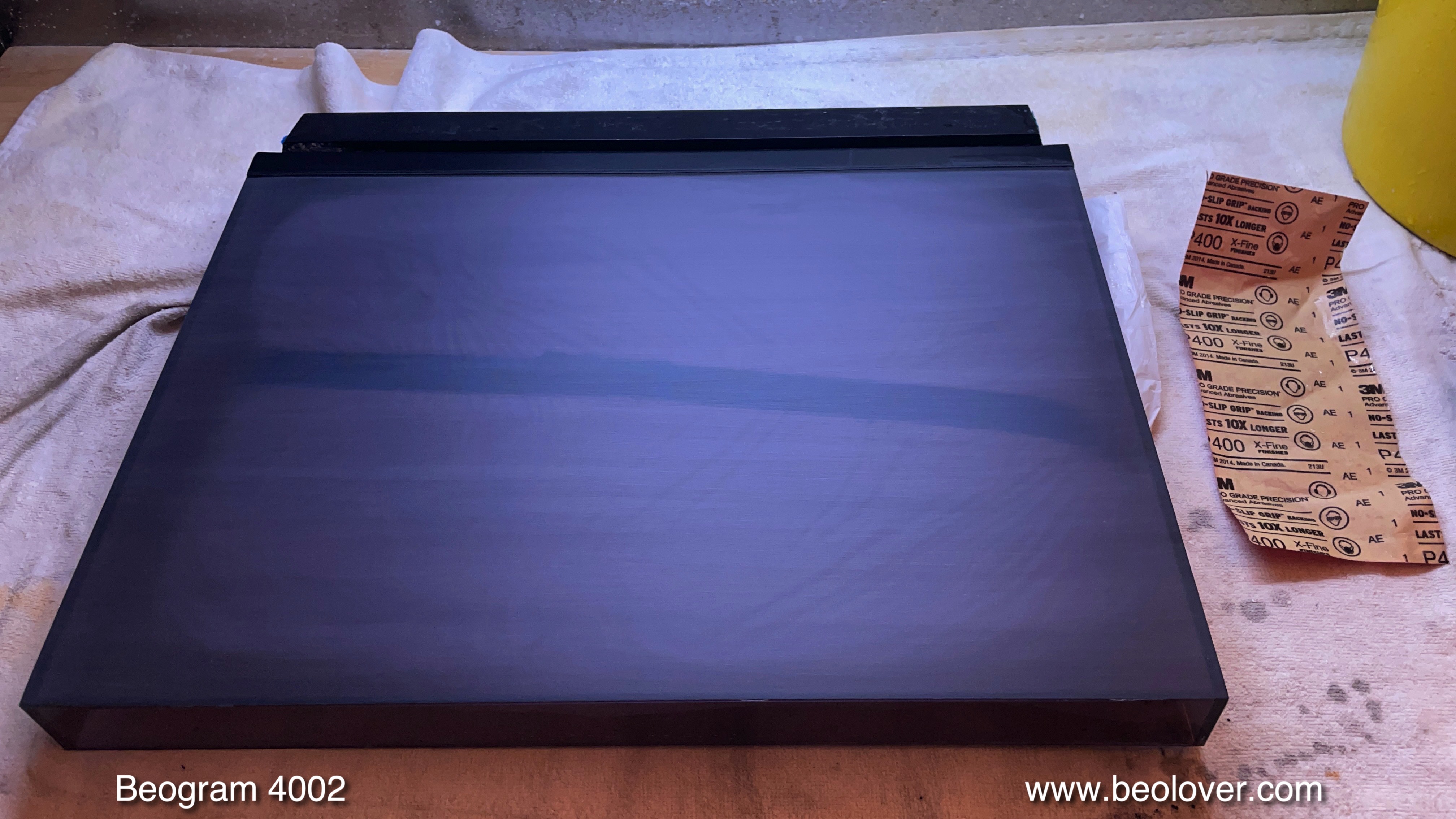
This post is a follow up to the initial 'first assessment' post that discussed the overall condition of this Beogram 4002 (5523). This post describes the work that was done to return this Beogram to like-new performance. This shows the unit as received with the aluminum plates off:

As usual the first step was extracting the DC platter motor for re-infusion of its usually dry Oilite bearings. This shows the motor removed from the enclosure:
I disassembled it to get the bearings ready for infusion:
The bearings are the two small donuts upfront on the black bad. I immersed them in motor oil and pulled a vacuum:
Immediately strong bubbling started, indicative of air being withdrawn from the pores of the Oilite material. This escaping air makes room for oil to interdiffuse into the bearing. This process usually takes 2-3 days, and so it is a good idea to start it first thing when restoring a Beogram with DC motor.
The next step was cleaning and re-lubricating of the carriage and arm-lowering mechanisms. This shows the arm lowering mechanism consisting of solenoid and damper:
I removed all these parts
and cleaned them ultrasonically:
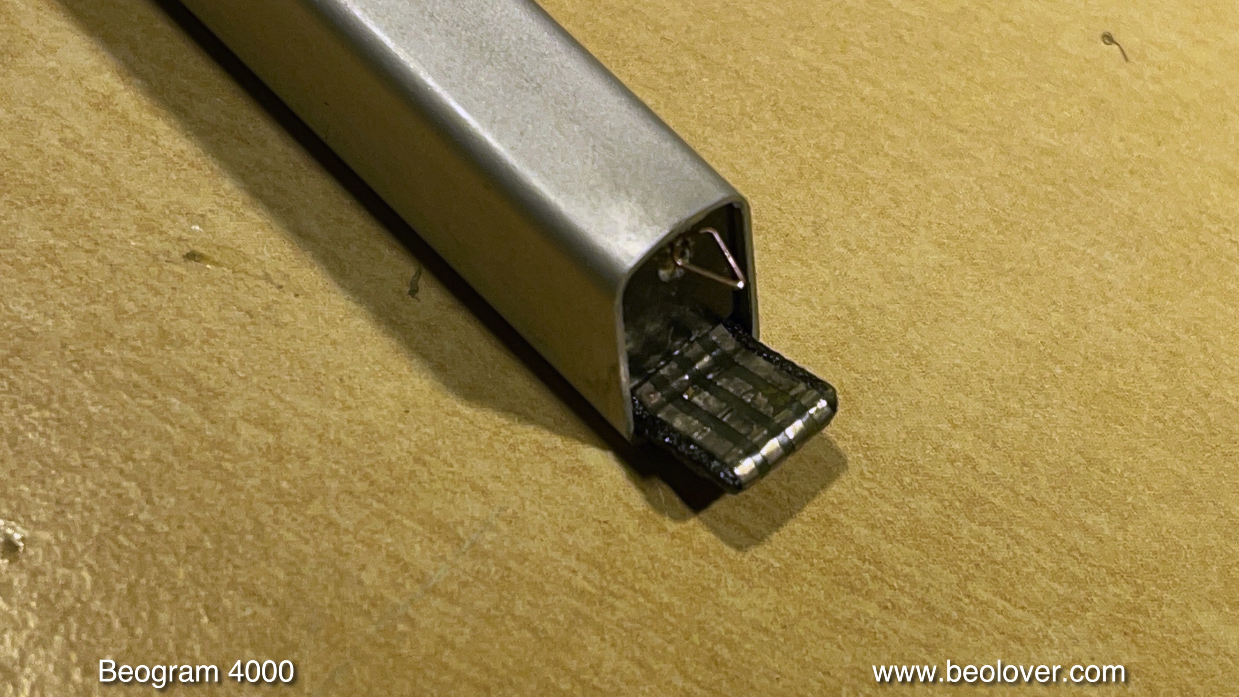
While working on the carriage it was a good moment to also update the tracking sensor light bulb with an LED assembly. This shows the original bulb housing:
Here you can see old and new next to each other. The LED in the replacement part is in the same location like the filament of the light bulb:
This shows the LED fixture implanted. The blue potentiometer allows fine-tuning the tracking feedback by adapting the LED brightness:
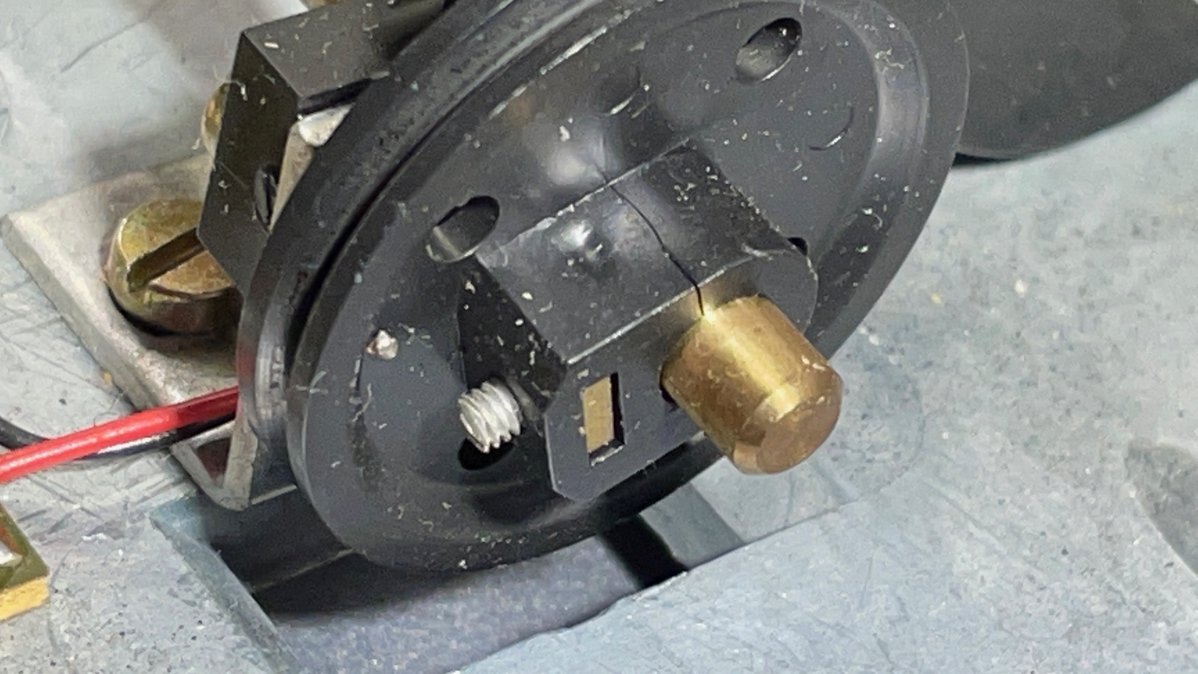
Another aspect of the restoration of the carriage section is the replacement of the usually cracked plastic pulley. Most crack due to material fatigue caused by the strain exerted by the set screw:
I usually replace them with machined aluminum pulleys:
Beolovely! On to the damper-to-arm linkage, which is often stuck due to hardened lubricants. Re-lubrication requires removal of the sensor arm assembly:
This shows the linkage removed:
While working on this assembly, it is a good idea to also remove the small copper pad that reduces lateral friction when the arm is up, and epoxy it back onto the base of the sensor arm. Its double sided tape is usually degraded:
Once the pivot point of the linkage has been lubricated and the sensor arm has been reinstalled, it is the perfect moment to adjust the horizontal parallelism of the arm:
This concluded the work on the carriage. Next up were the circuit boards. I now start out by replacing the two power transistors on the solder side of the board while the board is still installed. This shows one of them the TIP120 Darlington that acts as voltage regulator for the 24V rail:
When replacing it with a new TIP120, it is necessary to solder a 100nF capacitor between emitter and ground to prevent noise on the 24V rail. I saw this noise issue by now during several TIP120 replacements, and I think this may have to do with the fact that the modern devices may be faster than the originals. The 100nF cap stabilizes the output and the 24V rail is solid again:
After replacing the transistors on top, I removed the board.
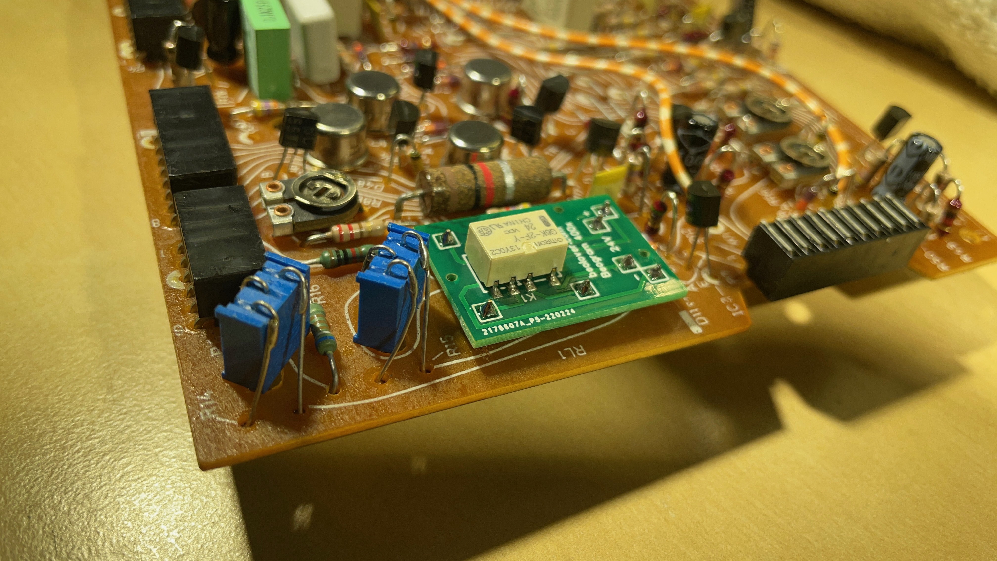
A detail shot of the 'RPM section' consisting of the RPM relay and the 33 and 45 adjustment trimmers:
This shows the rebuilt board:
and the updated RPM section:
The output board was next:
This board was interesting as it is really a 4004 output board, where the remote control section of the 4004 was not populated for use in the 4002. This 4002 must be one of the last ones made before B&O switched to the 4004. I usually replace the electrolytic capacitor that defines the time constant of the output relay and the relay itself, and I install a switch that allows connecting signal and system grounds for hum prevention. This is often helpful when connecting with RCA:
Then I replaced the light bulbs in the RPM panel, which are another (if minor) source of RPM inconsistency. Due to the heat emitted from the bulbs the trimmers in that panel can change their resistance and that changes the RPM. The cooler running LEDs seem to cure such issues. This shows the recently redesigned RPM panel LED boards:
They can be directly soldered to the spots where the bulbs are connected:
This RPM panel had been opened previously, and whoever did it used the original circlips when putting it back together. This is not a good idea since these are not meant to be re-used. This caused a loose attachment in this case. So I removed the clips to replace them with new ones for a more sturdy attachment of the aluminum panel. This gave me an opportunity for taking a picture of the business end of the LED boards as installed:
I put the panel back togehter with new clips and teflon washers:
While everything was removed from the enclosure it was the perfect moment to also take out the floating chassis and replace the disintegrating transport lock bushings
with new 3D printed nylon replacements:
These plug right into the holes from below and from the top:
This shows the lock reassembled:
At this point I also replaced the original reservoir capacitor with a new one:
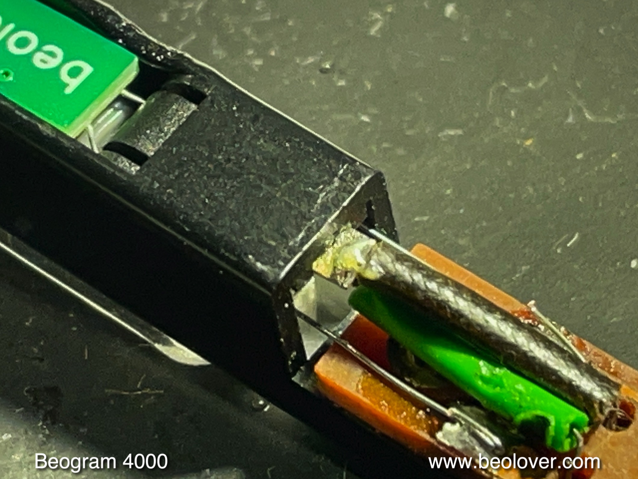
The remaining bulb to replace was the bulb in the sensor arm. It turned out that the bulb in the compartment was not original. The top bulb is an original one, while the bottom one was the replacement:
This shows the recently redesigned LED replacement assembly with its compartment insert that helps defining the LED location in the right spot in front of the lens that is at the bottom of the bulb compartment. It focuses the light onto the platter, to give the sensor enough intensity:
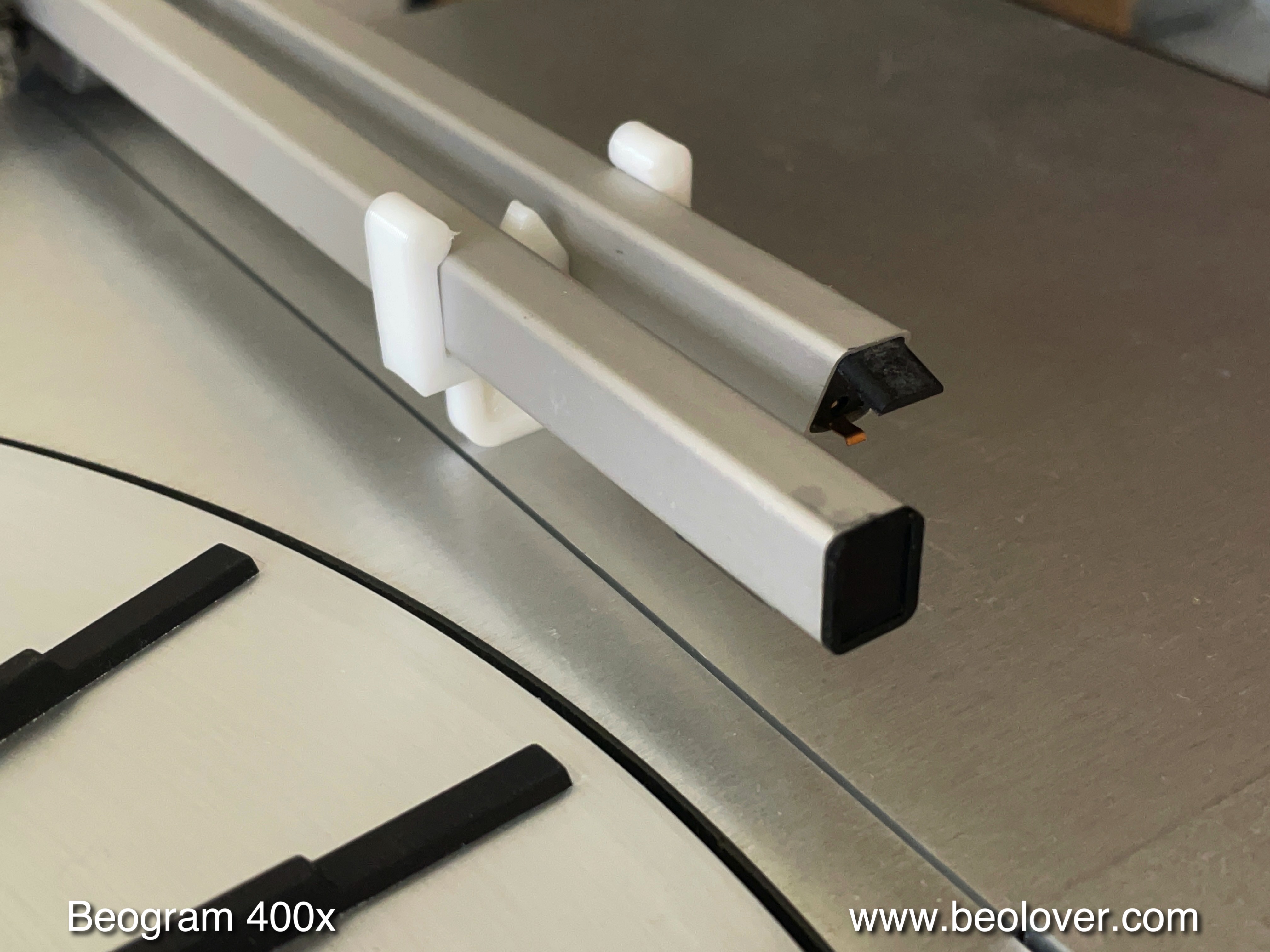
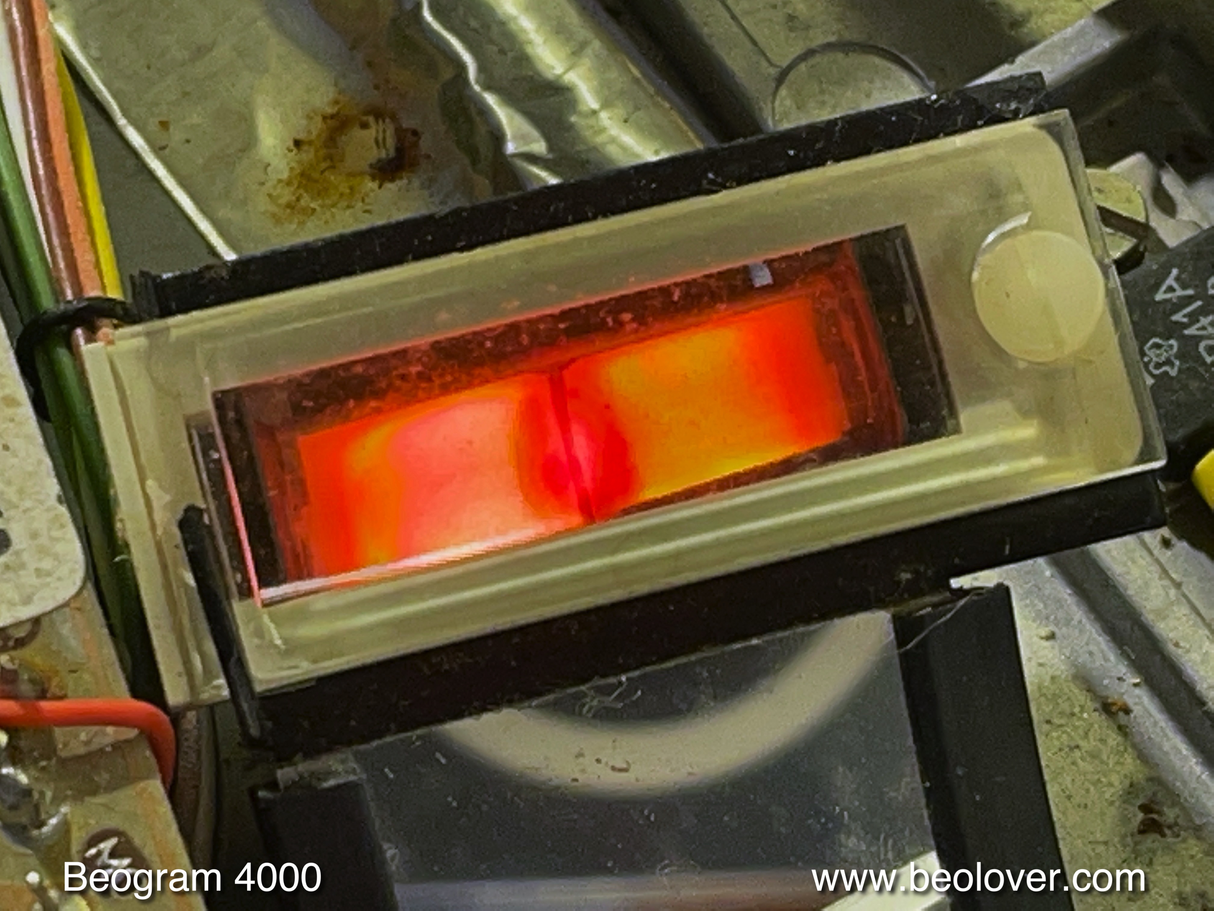
Here you see the LED in action: A nice red/orange logo color and a well defined spot on the platter:
I measured the sensor signal while the platter was spinning. This is what I saw on the oscilloscope:
A perfect trace with an amplitude larger than 6V and nicely defined troughs as ribs passed under the sensor. At this point the functional restoration was nearing its end. What was left were adjustments of the floating chassis, platter height, arm height, arm weight calibration and tracking feedback. I first adjusted the the platter and chassis, and then it was time to do the arm. This shows the original setup of the counterweight adjustment screw with its flimsy circlip to hold it in place:
This circlip does not really fix the weight in place very precisely, and so I usually replace it with a washer and a nut, which makes the setup more stable that it can withstand the rigors of shipping without changing the weight calibration:
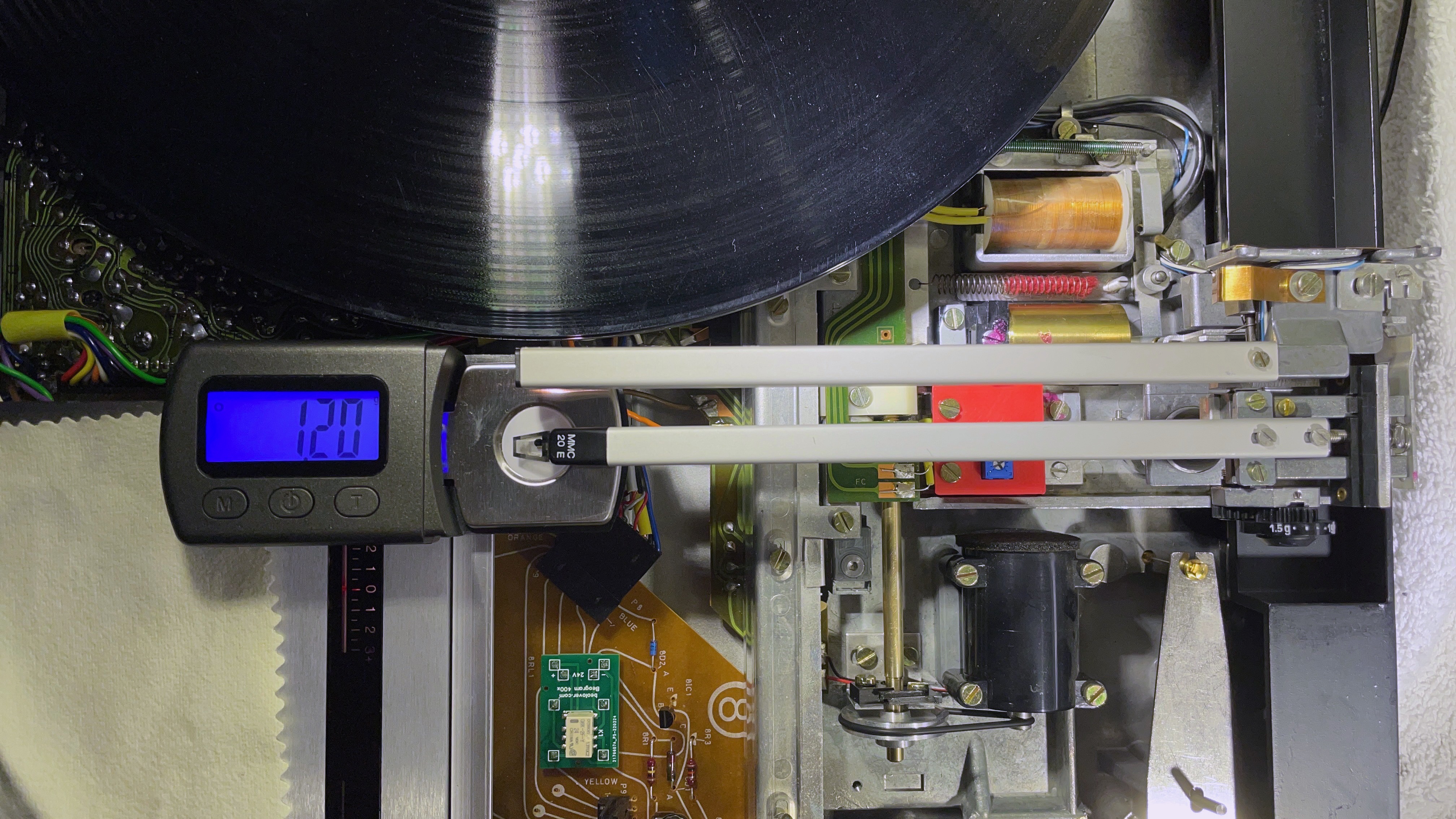
After this operation it was time to calibrate the weight scale in the arm housing around 1.2g for a standard B&O cartridge:
While this adjustment is nice to have done, it is usually best to not rely on the weight scale. Instead use a digital gauge to actually measure the tracking weight and simply adjust the wheel to whatever necessary for getting the proper weight for your cartridge.
After this adjustment I also adjusted the arm lowering limit. This is an important adjustment as it prevents catastrophic damage should the arm ever lower onto the platter due to a malfunction of the record detection circuit:
Finally, I adjusted the tracking feedback:
Then it was time to replace the original RCA plugs with new gold plated all-metal plugs for best shielding. This shows the original B&O plugs:
And here the very golden replacements:
After this I had a look at the motor bearings and found that the bubbling had stopped, indicating that the infusion process was completed. I extracted the bearings from the oil
and re-installed them in the motor. Then I put the motor back onto its place and ran the platter, monitoring the RPM with the BeoloverRPM device:
It allows logging the RPM in 10s intervals over extended periods of time. Perfect for detecting intermittent RPM issues. This is the curve I measured after about 24 hrs:
This is pretty much as good as it gets with the DC motor Beograms! Perfect!
The last step before giving this deck its first spin was the installation of the Beolover Commander remote control module. It allows controlling all functions without ever needing to touch the precious and easily damaged keypad. It also adds auto-repeat and fast scanning capabilities in a similar way as found in later Beogram 800x turntables:
See here for more information about the Commander if you are interested in getting one for your Beogram. It installs 'plug-and-play' without soldering in DC Beogram versions (Type 551x and 552x).
And now it was finally time to play a first record on this restored Beogram 4002! I selected a recently acquired album by Deodato, "First Cuckoo", which he recorded in 1975 (MCA 491). My favorite track is the cool and smooth "Adam's Hotel" on side 1. Perfect for listing while restoring Beograms! Of course this record was cleaned ultrasonically using a CleanerVinyl ProXL System. I love Deodato covers! This one in particular struck my interest. Perfect together with this lovely like-new operating Beogram 4002, which may have been manufactured a couple years after this album came out:

Beolovely! I will now play this deck for a couple weeks more to make sure there are no intermittent issues. This will also give me some time to polish the scratched hood to a decent state that this Beogram will appear in an almost new condition when everything is done!