Featured Post

Beolover SyncDrive: DC Platter Motor Replacement for Beogram 4002 and 4004 (Type 551x and 552x)

Late Beogram 4002 and the 4004 (Types 551x and 552x), which have DC platter motors instead of the earlier synchronous AC motors usually suff...

Showing posts with label signal. Show all posts

Saturday, May 28, 2022

Beogram 4000: Restoration and Exploration of Photocell Function in Sensor Arm

I am making good progress with the restoration of the Beogram 4000 that I recently put on my bench. While it seemed on first contact that this unit had escaped 'creative human interaction', I had to learn that it had been worked on by a tinkerer, and that a little bit of a mess had been made of the sensor arm insert that houses the light bulb and the photocell that measures the presence of a record (or rather its absence by detecting the intermittent reflection caused by the black ribs on the platter). My sensor arm LED installation video for Beogram 4002/4 explains in more detail how the circuit works if you are interested. It is pretty much the same circuit in the Beogram 4000.

When I pulled out the sensor arm compartment it immediately became clear that someone had been 'in there' before me: One wire of the photocell was not connected, the other was mangled (from not being careful when pushing the compartment back into the aluminum profile)

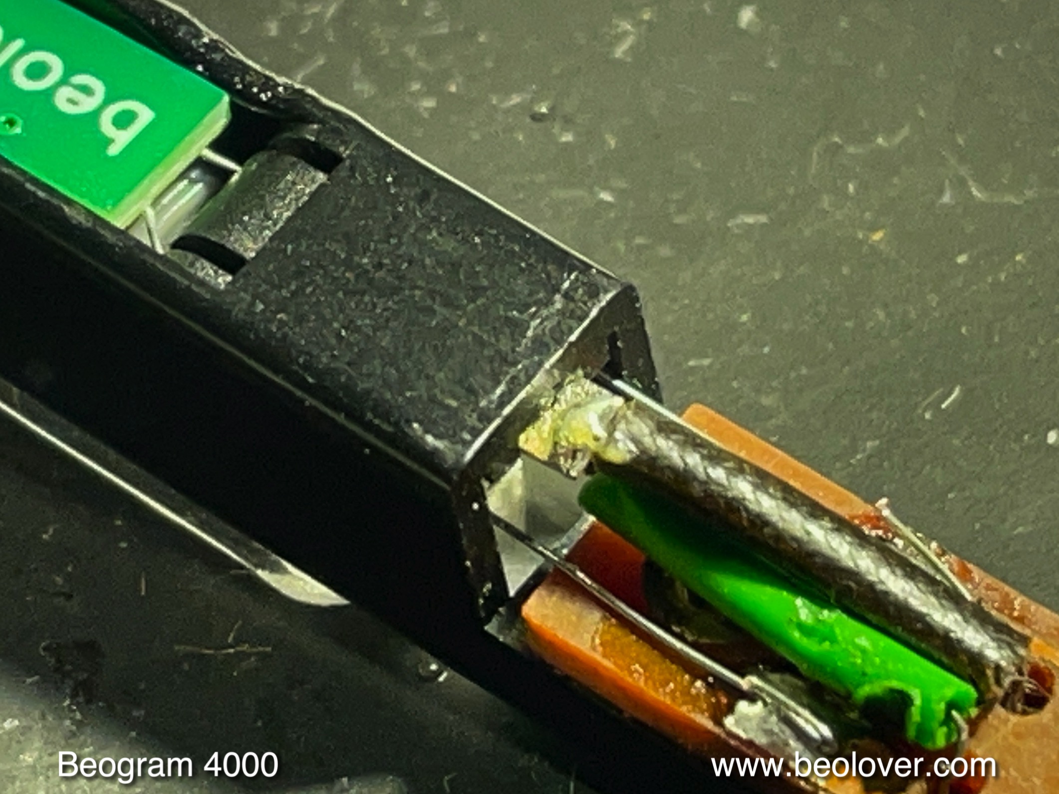
and there was some heat damage to the lens insert that focuses both the light emitted towards the platter, as well as the reflected component. This heat damage likely occurred from not being careful with the soldering iron. Amateur hour! Luckily the lenses themselves were not damaged:
I was able to extract the missing wire from the aluminum tube with some narrow tweezers and reconnected it. Then I removed the non-spec light bulb that had been installed (probably disabling the arm lowering circuit due to its non-spec current draw), and I replaced it with a Beolover LED insert (see above video for more details):
Then I adjusted the bias of TR14 to yield 1.8V at the collector 
and installed the adjusted trimmer on the component side that it not interfere with the platter:
Then I measured the sensor response with the oscilloscope and got only a minuscule signal from the ribs passing underneath the sensor of maybe 100mV amplitude. Unfortunately, I forgot to take a picture of the trace. So you gotta believe!...;-). I removed the sensor compartment again, and I had a closer look at the photocell side of the compartment. Usually the photocell is o.k., but here we see that it was not in its correct position (the upside down 'U' in the top rim of the compartment opening). Instead it was hanging down at a ~45 degree angle:
This explained immediately why the signal was so low: The light was not focused on the sensor anymore. I extracted the part:
Then I took the insert to the garage and carefully Dremeled some of the melted mess to make the sensor fit again properly into the aluminum tube:
After checking the sensor by connecting a multimeter in voltage setting to the leads and measuring a promising 0.5V in front of a strong LED lamp, I decided trying installing it to see if it would still work properly. My bench test had revealed that the sensor yielded more voltage on one side than the other (0.4 vs. 0.5V), and so I installed it with the stronger side towards the lens. This resulted in a reversed polarity of the wiring that came about 'naturally' and I did at this point not understand that the polarity matters. The installation of the sensor was done by putting dabs of contact cement in the compartment and on the sensor, and after 10 min drying time carefully pressing the sensor into its slot as shown here:
After soldering the leads I tested the sensor response and I still got a 0.4V signal when shining light onto the lens compartment:
So far so good! The delicate photocell seemed to have been saved, and the need for installing a modern phototransistor averted. But when I tested the sensor signal at the collector of TR14, I saw this signal, which looked inverted compared to the expected trace shape:
It immediately dawned on me that the polarity of the cell matters for this circuit and so I reversed the red and blue wire (I did not want to mess with the cell itself more than necessary)
And tried again. And now the signal looked very good:
A larger than 3V amplitude is excellent and more than enough to guarantee proper record detection. I hope I will soon play a first record on this lovely Beogram 4000!


Tuesday, February 5, 2019

Beogram 4004 (5526): Repair of Record Detection Circuit and a New Reservoir Capacitor

I started working on the Beogram 4004 that I recently received. I decided to look into the 'does not lower arm at LP set-down point' issue first.

***I recommend downloading the Beogram 4002/4 service manual with the circuit diagram for reading this post.***

Usually, when a 400x Beogram does not stop at the LP point after pressing START (with a record on the platter), there are two standard causes:
1) It does not detect the record properly, or
2) the carriage position sensor does not work.

#2 is easily eliminated by watching if the deck switches to 45 RPM once the arm sweeps past the 7" singles setdown point. If it does, the position sensor is most likely up to the task.

The 4004 did the 45 RPM switch, i.e. it was time to look into the record detection circuit. The record detection circuit essentially needs to pass three tests:

1) Does the light bulb in the sensor arm work, and is it the correct bulb with the right current draw?

2) Does the platter induce a proper ~5.5-6V amplitude signal at the collector of TR3?

3) Does the circuit put out the proper signal at the collector of TR6 (~15.5V when there is a record; ~0V when there is none) when a record is on the platter?

Since the light bulb was working (lit B&O logo), I measured the voltage at the Collector of TR5 that drives the bulb and it showed 8.5V (spec is 9V, but that is o.k.). This voltage is used by the circuit to put out a 'no record present' signal when the bulb is dead (the voltage would be close to 21V in that case, which would permanently turn on TR6, i.e. its collector would be 0V - saying 'do not lower the arm'. This is a safety feature, since without it a dead bulb would give the sensor the same impression as the presence of a record, and the arm would be lowered on the platter.

With regard to #2, it is a good idea to check the DC voltage at the collector of TR3 first and measure if it is close to the prescribed 4V. This voltage is necessary to ensure that the sensor signal has a 6V amplitude when the ribs of the platter pull by beneath it. I measured 2.1, which was very low. This meant I needed to replace the biasing resistor R26 with a 2M trimmer for adjusting the bias of TR3 (in essence quench some of the CE current to achieve a higher C voltage). This is a very common issue in the 400x, and implanting the trimmer usually allows adjusting the bias to get 4V at the collector. I put in the trimmer and tried to adjust the collector voltage:
Unfortunately, even by completely maxing out the 2M resistance on the trimmer, I was only able to get to 3.4V. This meant that TR3 had an unusually large Hfe. In absence of an even larger trimmer (and the rule of thumb not to use large resistances/very small currents in such circuits if one can avoid it) I decided to put a new BC547B transistor in. This fixed it:
I measured the Hfe values of both transistors, and the original 548C had about 750, while the Hfe of the new one was only 430, which allowed the 2M trimmer to do its job.

While it was a good idea to fix the TR3 voltage, this was unlikely to have fixed the issue, since a too small sensor signal causes the opposite effect: It always detects a record whether there is one or not, i.e. the arm gets lowered onto the platter if there is an issue with the sensor signal.

The next step was to check on the output of the detection circuit, i.e. I needed to measure the voltage at the collector of TR6 when the carriage reached the setdown point. I did, and the voltage remained close to 0V, indicating that the circuit was not doing its job. First I thought TR6 was bad, but my transistor tester gave it a passing score. This meant something else was pulling the voltage down to zero.

I started the Beogram without TR6 in place. This essentially should tell the circuit "record present" since this causes the same situation like a turned off TR6. I measured the voltage again at the vacant collector terminal of TR6...and it was close to 0 volt again! So clearly there was a short somewhere. The most direct connection to 0V is probably via a shorted out C19 that would pull the collector pad down to ground via R41. I measure the capacitance of C19 in situ with my BK Precision 879B LCR meter, and it yielded 4.7 Ohms! This caused me a bit of head scratching, since there is essentially no other good path for this short circuit to happen in this circuit. I finally measured the resistance across C19 with my multimeter, and I got a stable reading of 132 Ohm! That should not happen with a working capacitor. So I took the capacitor out and replaced it with a new one. And the circuit worked again.

I thought this capacitance measurement was an interesting lesson. I measured the cap with my multimeter's capacitance setting, and it showed 0F. So it seems that the frequency based measurement method has hits weaknesses, when it comes to measuring borderline dead capacitors. The 879B did show an ESR value of 11 Ohm on this capacitor, which is very high. This should have tripped me off right away, but in the fog of battle...anyway, an enjoyable evening with a Beogram 4004 is coming to an end!...;-).

But wait, this Beogram had one more issue to rectify: The reservoir capacitor. Whoever tried to fix it before hot-wired a new reservoir cap of the cheapest kind into the unit:
I replaced it with a Beolover capacitor assembly that fits precisely under the mounting strap of the original one:
Beolovely again!


Monday, November 30, 2015

Beogram 4000: Installation of a New Gold Coated DIN5 Plug and a Grounding Switch

The beautification of the Beogram 4000 that I am restoring right now continues. I installed a grounding switch and a new gold plated Neutrik DIN5 plug. The grounding switch allows to combine signal and system grounds of the Beogram. This essentially allows to switch between the grounding scheme of the later 4004 models and the 4000/4002 set-up where system and signal ground are separated. Depending on the amplifier set-up it can be beneficial to be able to select either one to avoid the formation of ground loops that can cause humming. I recently made a post that illuminates this in more detail.

This shows the switch installed. The shown orientation corresponds to the original 4000 set-up with separated grounds. Flipping it to the left would connect both grounds:


Here are a few pictures of the DIN5 replacement. This shows the corroded original plug:


And here is a picture of the new plug:

Beautiful! this shows the leads as connected on the inside:

Good to know that the precious MMC signals can now travel unimpeded!


Sunday, November 8, 2015

Beogram 4002 (5513): Installation of a New Output Relay and a GND Switch

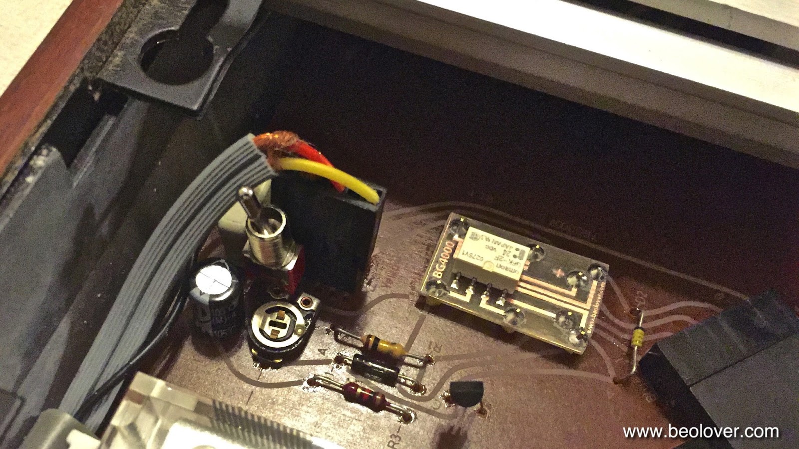
While I was testing the Beogram 4002 (5513) that I restored in recent weeks I realized that the output relay once in a while would not open up after the tip touched down, hence, preventing the audio signal from reaching the amplifier. Luckily the relay is the same type that is used for RPM switching in both 4002 and 4000 models. Therefore, I was able to use the breakout board that I recently developed for replacing the RPM relay in a Beogram 4000 with a modern encapsulated SMD signal relay.

While I installed the new relay I took the opportunity to also install a switch on this board that allows to tie signal and system grounds to deal with humming problems if necessary. Depending how the amplifier is setup it can become advantageous to tie the two grounds together to prevent the formation of grounding loops and/or open leads that can introduce ambient EMI into the sensitive phono preamp input. 

This shows the original relay:

And after installing the SMD replacement and the switch: 

This shows the board after installing it in the Beogram and replacing the plug that connects the cable:


Saturday, September 12, 2015

Beogram 4000: Installation of a Grounding Switch That Allows to Connect System and Signal Grounds

The last Beogram 4000 that I restored had a strong hum while playing when I connected it to my Beomaster 6000 4-Channel phono input. This was fixed by simply connecting signal and system grounds. While I was not able to fully figure out why the hum occurred, I thought it wise to install a switch with which one can choose between the original grounding set-up with separate system and signal grounds (which typically results in a connection between them in the amplifier circuit) and a direct connection between the two right at the 4000 output. My original post about this procedure contains a detailed discussion of the electrical setup. I thought this to be a useful upgrade for any 4000 and so I decided to put a switch also into this one. Here are a couple pictures to document the installation of the switch on this Beogram 4000.

This picture shows the original setup. Signal and system grounds are connected separately to the shielded DIN cable. System ground is connected to the shield, while the signal ground is connected to the inner lead-shields:

Here is the set-up with the switch allowing the user to switch easily between the two setups. I also cleaned up the soldering mess of the as-found configuration:


A discussion of the grounding strategies of the later Beogram 4002 and 4004 models is included in this video (they actually went from the original separate grounds model to connecting them in the 4004, i.e. my switch simply implements both strategies in one set-up allowing a choice between them):

Thursday, September 10, 2015

Beogram 4000: Adjusting the AC Motor Voltage and Measuring the Voltage Differences Between the Phases

Today I adjusted the AC motor of the Beogram 4000 that I am currently restoring. The manual prescribes to adjust the main phase of the motor to 6V (RMS) and the frequency to 42.3 Hz for 33 RPM. This is easily done with an oscilloscope. To see both phases the probes can be simply connected to either side of the phase capacitor:

Adjustment procedure: First set the 33 RPM trimmer on the control panel to its null position (i.e. vertical). This ensures that the adjustment of the RPM offset potentiometer on the main PCB can now be adjusted to yield a 42.3 Hz motor signal when the control panel trimmer is nulled out. This ensures that the user can both trim the pitch for the same frequency deviations in + and - directions. Once the frequency is set the MOT potentiometer can be adjusted. It is important to do it in this order, since the frequency affects the amplitude of the signal. We are working with an analog oscillator here...;-).
Once everything is adjusted the oscilloscope should show about this:

The yellow trace is the main phase and the green trace is the 2nd phase. It is interesting to note that the 2nd phase has a smaller 5.3V (RMS) amplitude. This concludes the adjustment.

When switching the motor to 45 RPM one sees this:


Note that the 2nd phase is now much larger, about 8V (RMS), while the main phase dropped a bit to 5.6V (RMS). The manual also wants 6V (RMS) here, but there is nothing one can do about this since the MOT trimmer determined both frequencies, and 33 RPM is probably for most people the much more important speed. 

There is an interesting detail I noticed about the RPM trimmers on the control panel. The 45 RPM trimmer is nulled when the correct frequency of 57.3 Hz is adjusted with it:


When I took the control panel apart for converting it to LED illumination, I noticed that the red inserts that allow the adjustment of the trimmers with a screw driver are different for 33 RPM and 45 RPM: The driver slot is at an off-angle for the 45 potentiometer, while for the 33 trimmer it is symmetrical. Again, the designers gave the 33 speed priority and made a small compromise for 45: The consequence of this off-angle is that the 45 speed can only be adjusted by about a quarter turn to higher speeds, while one can go about a half turn to lower speeds. All this was probably dictated by the need for using standard resistors and trimmers in the Wien oscillator feedback circuits, which prevented them from designing the circuit in a way that the 45 trimmer would be exactly in its center position for an exact 57.3 Hz.
With modern resistor values one could easily fix this since nowadays one can buy resistors with almost any value. Apparently not so in 1973. Of course if one would now fix this by replacing the resistors, the trimer slot would be at an angle, which would not look good. What a conundrum! Will I be able to sleep tonight?? This is Beolove!..;-)


Friday, December 26, 2014

Beomaster 8000: Signals at IR Remote Receiver Test Points

After the remote receiver came alive again in the Beomaster 8000 that I am currently restoring, I decided to take some measurements at the test points for future reference. I thought this memo might come in handy the next time there are some problems in this area.

Below is the relevant section of the circuit diagram. The IR sensitive diode 6D27 changes its impedance when IR light impinges. This drives the damped 41kHz resonator formed by L1/C2/R1. IC1 drives the signal into the input of IC2 (TP5), where it is amplified. The signal emerges from the amplifier at pin 3 where it has a 12V amplitude (TP7). The 41kHz modulation is removed in the filter formed by R16/C27 and a cleaned up digital signal containing only the bits of the remote codes is forwarded by TR25. TR26 finally changes the signal to a 5V compatible signal via a pull-up on the processor board (PCB#9)


It is interesting to note that this entire circuit is nowadays integrated into the receiver package (example IRM3638), which has pretty much the same form factor as the simple IR diode D27 that is used in the Beomaster 8000. Amazing progress in a couple decades!


This is the table of remote codes from the service manual:


It is evident that all codes start on a 1, which represents the start signal for the transmission and its evaluation in the microcontroller. It is interesting to note here that the signal of the remote is fed into pin 24 of the 6500/1 microcontroller, which is on its port B. Only Port A is interrupt capable on this processor (S. A. Money: Microprocessor Data Book) and it is completely used for the keyboard readout. This suggests that the remote function is fully software implemented. Anyway, after this trip down the memory lane (I am a proud Commodore 64 veteran...;-), here are the oscilloscope signals that I measured while pressing continuously 'Volume Up' (10100111) on the Terminal:

TP5 (input to amplifier) - pretty strong 700 mV signal, which is no surprise, since the Terminal was about 20 cm away from the IR diode (note the 20ms timebase...the other two pics below were measured at 10ms):


TP7: Output of Amplifier (signal is still modulated, but amplitude is now ~12V):


TP8 (after removing the modulation and translation to 5V a clean digital signal emerges):


Friday, November 28, 2014

Beogram 4004: Characterizing a MMC20EN Cartridge with an Analogue Productions Test LP

I recently bought 'The Ultimate Analogue Test LP' from Analogue Productions. I felt I needed to be able to characterize the output of my cartridges and I read about this LP. It is a heavy duty 180g high-quality vinyl that has all the relevant test tracks for basic measurements.

I connected the oscilloscope to the DIN5 connector via a DIN-to-RCA breakout and two RCA-BNC adapters. This allowed me to form a shielded signal path from the output of the Beogram 4004 to the oscilloscope. However, the measurement was still pretty noisy, so I resorted to using a low pass coupling for the trigger and averaging. This gave me usable traces. Here is a shot of the oscilloscope screen on the 1 kHz test track:


It is obvious that the MMC20EN cartridge that came with my Beogram 4002 puts out a well balanced signal on both channels. The peak to peak amplitude of the 1 kHz signal is about 15 mV. This also seems to be a pretty good way to calibrate the RPM of the platter...

Here is a shot of the 100 Hz track (timebase is 10 ms/sq):


As expected the amplitude is considerably lower (maybe 4 mV without the noise) than for the 1 kHz signal due to the RIAA pre-emphasis. This is necessary at low frequencies to keep the groove width reasonable (Faraday's law prescribes that the induced EMF is proportional to the change of the magnetic field, which in turn is proportional to the velocity of the moving magnet, iron or coil in a cartridge). I found an excellent summary that explains the background behind the RIAA curve and the historic path towards it. The article is by Gary A. Galo and can be found here.

In short, the RIAA curve lowers the amplitude progressively towards lower frequencies to reduce the groove width (otherwise long playing records would not be possible). At high frequencies the amplitude is increased to stay ahead of the noise, which, due to its high frequency content is an effective EMF generator. Hence the signal amplitude needs to be a few magnitudes larger than the noise amplitude, that in the amplifier signal + noise can be reduced together, thereby reducing the noise relative to the original signal level. This is a similar approach as is used in Dolby noise reduction systems. 

The 10 kHz track on the Analogue Productions LP produces a standardized -20 dB amplitude (i.e. 10x smaller than the other two tracks, which are at 0 dB. 0 dB apparently corresponds to a 7 cm/s stylus velocity, as suggested on the LP sleeve. Here is the (pretty noisy, disregard the Freq measurement indicator) measurement (timebase is 100 us/sq):


Without the noise the amplitude might be about 10 mV or so, i.e. it were at about 100 mV at 0 dB. That would give us about a factor 7 relative to the 1 kHz signal. 20*log(7)=16.9 dB, which, considering the noisy measurement, is reasonably close to the RIAA curve (from stereophile.com, the blue curve is the curve used on records, the red one is an idealized 6 dB/octave curve, which would be best, but cannot be implemented due to practical reasons), which suggests a pre-emphasis of about 13 dB at 10 kHz:


The 100 Hz measured amplitude above is also reasonably close to the curve: 20*log(4/15)= -11.5 dB (compared to about -13 on the curve....

All in all another interesting evening at Beolover's lab...;-)