Featured Post

Beolover SyncDrive: DC Platter Motor Replacement for Beogram 4002 and 4004 (Type 551x and 552x)

Late Beogram 4002 and the 4004 (Types 551x and 552x), which have DC platter motors instead of the earlier synchronous AC motors usually suff...

Showing posts with label remote. Show all posts

Monday, November 18, 2024

Beogram 4002 (5513): Installation of Upgrades (Beolover SyncDrive and Beo4 Commander Remote Control)

This post describes upgrades that I installed in the Beogram 4002 (Type 5513) that I just restored for a customer in California. The restoration process of this unit is posted here.

This unit received both the Beolover SyncDrive platter motor replacement and the Beo4 enabled Beolover Commander remote control

The SyncDrive directly replaces the DC platter motor of all Type 551x and 552x Beograms. These Types often suffer from intermittent RPM stability issues due to dry motor bearings, oxidized RPM relays and trimmers. The Beolover SyncDrive completely bypasses the motor control circuitry, i.e. it is unaffected by the above issues. It also improves the longterm RPM stability due to its digital control system. Installation of the SyncDrive is completely plug and play. No soldering required.

This shows the SyncDrive module bolted into the mounting posts of the original DC motor:

Next came the installation of the Beo4 enabled Beolover Commander remote system. It also installs plug-and-play without soldering. The remote module essentially taps into the keypad connector and so can control the Beogram in parallel with the keypad, which remains functional. The Beo4 version allows seamless integration of a Beogram with a Beo4 or Beoremote One controlled B&O system.
This shows the module installed together with the Beo4 remote switched to Phono:
And then it was time for a little victory lap with this beautiful restored Beogram 4002! I selected a recent acquisition for my vinyl collection, 'Man to Man' by Hot Chocolate (Big Tree Records BT89519). This wonderful album came out in 1976, a perfect contemporary to this Beogram! My favorite track is probably "Heaven Is In The Back Seat Of My Cadillac". Very funky!...;-). Of course this record was cleaned on a CleanerVinyl ProXL setup, which restored it to its original glory with quiet black space and music tracks largely devoid of clicks and pops! 
While I was enjoying some more Hot Chocolate, I focused on the installation of a new reproduction aluminum trim on the brand new hood that this Beogram came with. This shows the hood together with the aluminum trim:
I usually align the trim prior to glueing with my custom designed alignment aids that clip into the hood sides. A strip of residue free blue 3M tape allows making a pencil mark across strip and hood. Here a close-up of one of the alignment pieces:
After glueing the strip in place on top of the hood, the sides can be bent down. Beautiful!:
I will now listen to some more records with this Beogram 4002, and then it will be time to send it back to its owner in California!


Friday, June 14, 2024

Beo4 Enabled Commander Remote Control: Seamless Integration of Beogram 4002 or 4004 with More Recent B&O Systems

A few months ago, Dirk, a fellow Beolover in Berlin, contacted me and suggested that it would be a nice thing being able controlling his Beogram 4004 with a Beo4 remote control. He has a Beosound 9000 in his living room, and wanted to integrate his Beogram in a way that it ideally would behave as a 'Beolinked' source.

I appreciated this idea and figured out how to modify the existing Beolover Commander remote. Basically, it needed a 455kHz capable IR receiver for communicating with a Beo4 and then I had to figure out how the Beo4 'ticks' in terms of codes it sends out in certain operational circumstances and rewrite the firmware.

Since the Beo4 is a fairly complex remote control with many modes, this was not trivial. But in the end I think I was able to arrive at a useful point, where the Commander equipped Beogram would pretty much behave as if it were connected to the Beosound via Beolink. 

I made a short video that demonstrates this system. The video contains footage that Dirk sent me. It shows how his Beogram interacts with his Beosound. He even figured out how to make a Beoremote One work with the Beo4 Commander! Very awesome! Enjoy:


The Beo4 Commander is available at the Beolover Store if you want to try this at home!..;-).


Wednesday, May 22, 2024

Beogram 4002 (Type 5513): Full Upgrade with SyncDrive Platter Motor, Commander Remote Control and Internal RIAA Pre-Amplifier

My customer from Kentucky decided to give his Beogram 4002 the 'full treatment' and asked me to install all three Beolover upgrades that are currently available for the DC platter motor Beogram types:

  1. SyncDrive synchronous platter motor: The SyncDrive improves RPM stability and consistency and levels DC motor Beograms up to AC motor performance.
  2. Commander remote control system: The Commander is the perfect addition to 4002 and 4004 Beograms for protecting their fragile keypad coatings. It uses an Apple remote for controlling all functions of the Beogram. In addition the Commander adds auto-repeat functionality and an improved << >> scanning function.
  3. Internal RIAA pre-amplifier: The Beolover RIAA replaces the original output board and allows directly connecting the Beogram to any high-level input of modern amplifiers, like CD, DVD or AUX.

All three upgrades are plug and play, i.e. there is no soldering required for their installation. I started with the SyncDrive. This shows the original DC platter motor still installed:

The SyncDrive bolts to the same mounting posts and it only needs one cable connection to the main PCB:
Then I removed the keypad to get to the output board. This shows the original board still in place:
The Beolover RIAA pre-amplifier has the same form factor like the original board. Simply plug the wire harnesses into matching board headers on the RIAA board. At the same time I also plugged the Commander remote control board into the keypad header on the main board:
The final step was putting the keypad back in, plugging its connector into the Commander board and bolting the auto-repeat indicator in with the keypad screw:
And then it was time to play this lovely updated Beogram 4002 a bit more. I selected another great Milt Jackson vinyl, "Olinga", which was recorded in 1974 on the CTI label (CTI 6046). Before play, this record was ultrasonically refreshed using a CleanerVinyl ProXL setup reducing clicks and pops to a minimum. 
Beolovely!
I will now play this deck for another week or so and then it should be time for sending this upgraded Beogram 4002 back to its owner in Kentucky!


Sunday, April 23, 2023

Beogram 4002 (Type 5504): Installation of Commander Remote Control Module

This post discusses the installation of a Beolover Commander Remote Control Module in a Beogram 4002 (Type 5504) that I recently restored for a customer in Australia. This unit also already received an internal Beolover RIAA phono pre-amplifier.

This shows the commander Remote Module before installation:

The black three-wire appendage at the bottom is the IR receiver that gets fed through in-between the plinth and the enclosure of the Beogram (see pic at the end of the post) so the IR signal can reach the Commander Module. The narrow adapter board on the right is used to break the keypad contacts out for the Commander, that it can take over control of the turntable. The white wire harness makes the connection from this adapter to the Commander board. The red wired appendage on top is the auto-repeat indicator that gets bolted in with the keypad screw underneath the RPM adjustment panel.

Let's do the installation! This shows the keypad and the adjacent area of the main PCB where the Commander will be installed:
After removal of the keypad, the keypad PCB needs to be slid out of the keypad assembly. This reveals the solder terminals where the main PCB connects to the keypad:
For installing the narrow adapter board part of the solder needs to be removed to generate a smooth and flat 'landing strip' for soldering the adapter in. This is shown here:
I used a de-solder pump to remove the solder.
The next step is to place the adapter on this cleared area and solder it to two of the pads, preferably on either end: 
Tacked on like this the adapter pad can still be aligned and oriented properly.

***Note added in proof: After having installed this component a few times, I realized that it is best to solder the adapter into a position where the white plug socket is flush with the board edge. There are some keypads where the plastic part underneath the keypad is in a position that is a bit further to the left than normal, and it can interfere with the adapter if it is soldered too far inside the board perimeter).*****

Once it is in place (i.e. orthogonal to the solder pads, the solder pads match up well with the pads on the keypad PCB and the adapter sits flat on the pads with only minor gaps), then the remaining pads can be soldered:
At this point it is a good idea to plug the white wiring harness into the jack on the adapter board (support the PCB on the back of the jack while pushing the plug in):
If you do this at home, be careful to put the plug in in the right orientation. It is easy to bend the contact terminals in the jacks due to the miniature size of these connectors. This concludes the keypad modification. From here on it is plug-and-play. The next step is bolting in the auto-repeat indicator under the RPM indicator panel:
The red wiring harness is supposed to 'leave' the keypad via the cutout for the RPM panel wiring on the left. Now it is time to bolt in the Commander board. It simply bolts to the PCB screw that is next to the keypad with the included longer screw that replaces the original screw the Beogram came with.
Once the Commander has been bolted in it is time to make the wire connections. This shows the plug of the white harness. The way it needs to align is like shown here, with the connecting terminals on the upper end of the plug. Another indicator of proper alignment is that the white wiring goes 'flat' from the keypad adapter to the Commander board. If it is twisted, the orientation is probably 180deg off.
Once it has been carefully plugged in, the red harness of the auto-repeat indicator gets plugged in. Then the IR received needs to be threaded through the gap between plinth and Beogram enclosure:
There is a gap between the metal parts that are glued to the plinth, and that is where the IR wiring should go through. If done properly, the IR receiver will stick out like this from underneath the plinth:
And that is it. Now the Beogram can be powered up and the remote control should allow starting the Beogram with the "start/arm lift" button. This is a summary of the commands that are available:


Wednesday, November 23, 2022

Beogram 6000 (5505): Installation of AC-Motor Version of Beolover Commander Remote Control

This post discusses the installation of the AC-motor version of the Beolover Commander Remote Control into a Beogram 6000 (Type 5505) that I just restored. These are the links to the initial three posts that discuss the initial condition of the unit, its functional restoration, and the restoration and exploration of the CD-4 channel pre-amplifier.

This Beogram 6000 has an original keypad that is in almost pristine condition:

An ideal case for installing the Beolover Commander! I developed it mainly as a way to protect the Beogram keypads. They tend to loose their coating if they are used with direct finger contact. So the best way to protect them is to not use them! The Commander allows full control of the Beogram without ever touching the keypad again. It even adds some more functionality: It has a programmable auto-repeat function and adds the 'spin the platter for record cleaning' that is a standard feature in later DC motor Beograms, but is absent in the AC motor versions.

This shows the the Commander system for the AC motor Beogram 4002 versions:

The Commander remote module is controlled via a paired Apple remote. The pairing function can be cancelled if so desired, or necessary for integration of the Commander into a larger remote controlled system. 

This is a summary of the Commander functions:

The main difference between the DC and AC motor versions of the Commander is that there is no keypad connector in the AC Beogram versions since their boards are mostly wired directly together. This means a connector needs to be installed on the keypad PCB before the Commander can be plugged in.

So the first step is the installation of this adapter. It is shown here:
The first step is to remove the keypad, flip it over, and then slide the PCB out. This is how the keypad looks flipped around: 

Unfortunately, the above picture shows the PCB already slid out partially. In its 'fully in' position, the alignment tab catches the machined groove in the aluminum profile to hold the PCB firmly in the proper position:
This tab is spring loaded, i.e. you can simply pull it up with your fingernails, and then slide the PCB out:

Before moving on with the process, it is a good idea to put the keypad into a secure location to make sure it does not get scratched accidentally.

For the installation of the adapter the PCB needs to be flipped over

On the left side of the PCB there are the wire terminals. This shows them magnified:
This is where the adapter needs to be installed. The first step is to create a 'corridor' free of solder through the center of all the wire tabs as shown here:
There are some wires that connect at the back end of these terminals as shown here:
Usually, there is no other way than to remove the solder from these wires when creating the flat area for soldering the adapter in place. After installation of the adapter these wires will need to be soldered in place again.
This shows the adapter soldered onto the terminals. It needs to be vertical relative to the PCB and the end of the white socket needs to be about flush with the boundary of the PCB. Like so:


I usually tack the adapter to the PCB on two of the terminals and make sure it is well aligned. Then I solder the remaining pads together. It is difficult to remove the adapter once it is fully soldered in. So better make sure it is in the right place before putting all that solder down.

The next step is the installation of the Commander board. This shows it from the bottom:
The part that connects to the main PCB is the narrow tab on the right side. The raised edge on the far right end aligns the board with the edge of the main PCB. The bolt hole on the left side is used to bolt it onto the main board using the threaded hole that is used for the right PCB screw of the main board. It is located between the two blue trimmers I installed for adjusting 33 and 45 RPM.
This shows the Commander board in place. The original PCB screw needs to be replaced with the included M3x14mm screw due to the added thickness of the Commander board.:
It is important that the black remote receiver is fed in between the the plinth and the enclosure next to the front alignment feature of the plinth.
Once the board is bolted in, the keypad can be connected with the included white jumper:
This shows the connection to the Commander board in more detail 
and this the connection to the adapter board
It is important to note that the installation of the white jumper needs to be done carefully, since it is easy to bend the filigrane contact pins inside the sockets. In other words, the connectors need to be aligned properly before they get pushed in. This shows everything from the top:
Now the keypad PCB can be slid back into the keypad profile:

The final step of the installation is mounting the auto-repeat indicator PCB under the screw that holds the keypad in place. Since this is a Beogram 6000 which uses the CD-4 indicator integrated in the RPM panel, I had to modify the little PCB by cutting out a corner with sheet metal shears. This opened a path for the light emitted from the CD-4 indicator LED under the keypad.

After this I put everything back together and tested the Commander system. I selected one of my favorite Bob James albums, 'Lucky Seven' from 1979 (Tappan Zee Records, Columbia, JC36056). Of course this album was thoroughly cleaned with a CleanerVinyl ProXL setup using a multi-frequency ultrasonic cleaner before listening! This shows the Beogram 6000 in action together with the nice cover of this album: 
Beolovely! Soon it will be time to return this Beogram 6000 to its owner in the UK.


Monday, January 17, 2022

Beolover Commander Enables Control of Beogram 4002 or 4004 with the Beosystem4 and the Beo4 Remote

One of the great aspects of Beoloving is the amazing people one gets to interact with. Martin, a customer in Germany, recently acquired the Beolover Commander remote kit for his Beogram 4004.

After he had received and implanted it, he got in touch and asked me if it were possible to make the Commander work with any Apple remote, instead of just the paired remote I provide it with. Pairing means that the Commander only interacts with the included remote, but not with other Apple remotes that may be in use in a particular setting. This prevents unwanted crosstalk. 

The reason for this request was that Martin was up to something exciting, where the pairing feature was a hindrance!:

He wanted to integrate his Beogram 4004 with his Beosystem4 that he controls with a Beo4 remote. This is possible since the Beosystem4 can be set up to interact with 3rd party audiovisual equipment via a "PUC" table that can be loaded into the Beosystem4. PUC stands for "Peripheral Unit Controller". Long live the use of acronyms for impressing the uninitiated...;-).

Such a PUC table contains the information the Beosystem4 needs to send out codes destined for equipment manufactured by other companies. Like Apple. This means that the Beosystem4 can be setup to control Apple TVs, and since the Beolover Commander uses an Apple TV remote, the Beosystem4 can also control a Beogram 4002 or 4004, provided that the Beolover Commander remote module is installed.

But: The PUC mechanism does not provide for controlling Apple devices that are paired with a specific Apple remote, i.e. the Commander needs to be un-paired to make this work.

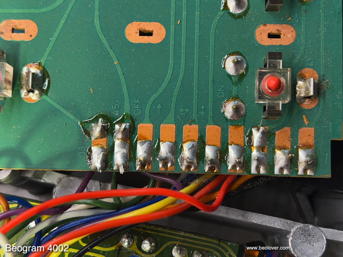
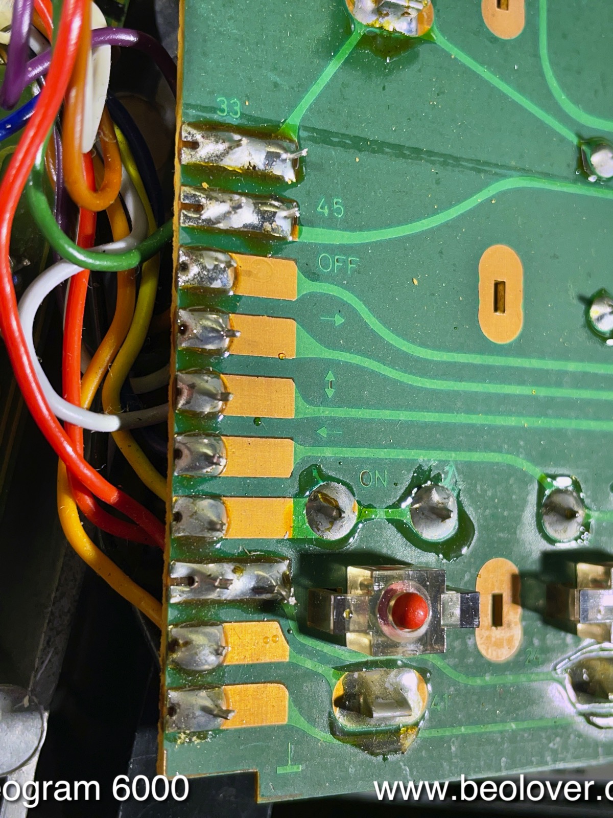
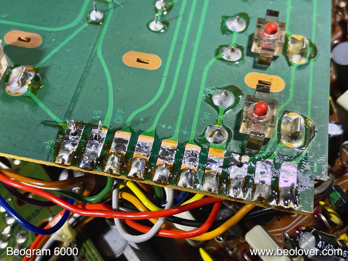
So Martin got in touch and I updated the firmware in a way that the pairing feature can be turned off by the user if so desired: Simply press the "Sweep right" button on the black ring 7 times until the Autorepeat LED flashes three times. Done. From this moment on the Commander will take commands from any Apple remote, not just the provided one. For re-pairing simply perform the pairing procedure by pressing the Menu and Select buttons for ~6 seconds until the 33 RPM scale light comes on briefly. If you want to do this and you bought your Commander before January 2022, you will need to send it to me for a free update of the firmware.

At this point you are probably curious how to set this up with the Beosystem4! Since the Beolover mentally mostly lives in the 1970s, I asked Martin to provide a step-by-step description of his process, which he happily provided. This is what he sent me (please, contact him directly if you have additional questions for he lives in the present and understands newer B&O equipment):

Martin's Set-up Instructions:

"The Idea was to connect my Beogram 4004 with my Beosystem4 for full remote control with the Beo4 remote. This will also work with multi-room option in your system. 

I’ve heard about the remote control commander of the beogram 4002/4 created by beolover (https://beolover.blogspot.com/2021/09/commander-remote.html

What I really like with B&O is 'one Remote for everything'. B&O is providing a 3rd Party control with PUC (Peripheral Unit Controller) on some Beovision and Beosystem. (i.g. Beosystem4, Beovision 11 and Beoavant, with Beosystem3, Beovision7,8 and 10. You'll need to get the PUC Table installed by your B&O dealer!) 

The only thing you need is an IR-blaster cable (can be ordered by our B&O dealer) 

After installing the remote control commander of Beolover you just need to bring the PUC IR blaster transmitter to the Commander IR receiver, and connect the audio cable of the Beogram via an RIAA pre-amplifier to your Beosystem/vision and configure the system accordingly.

Set-Up Process:

Step 1: Install the Beogram Commander Remote Control as shown in the video (https://www.youtube.com/watch?v=Pfhm93kIU1k&list=PLQ 7T0PlkOsiMEDx1rs1uoK496Ww38hqb8

Step 2: Connect the IR-Blaster to the Beogram. This shows a stock photo of B&O IR Blaster cables:

The Blaster transmitter end of the cable needs to be attached to the Commander IR receiver that pokes out from underneath the plinth:

This shows the 'wiring diagram' of the setup:


So it is quite simple to physically connect the Beogram with the Commander to the Beosystem4 controller!

Step 3: Setup:

1. Un-pair the Beolover Commander from its dedicated remote: 
  • The Beogram needs to be plugged in and in stop position (the arms are 'home' at the far right) 

  • Un-pair the Apple Remote: Press 7 times ’carriage 
to right’ (the right Function on the black ring of the Apple remote). 

  • The auto repeat LED blinks 3 times and the pairing feature is disabled. 

  • Now the Commander is un-paired and will take commands from any Apple TV remote
2. Configure the Input(AVIn) of the Beosystem/vision with the “Apple TV 2 and 3” PUC 
  • Press ‘menu’ on the Beo4. 

  • Select “SOURCE LIST” from the menu. 

  • Select “AV” source, press ‘red’ button for setup. 

  • Select “DEVICE”. 

  • Press ‘select’ on your Beo4. 

  • Select “YES” for operate the AV access with your 
BANG & OLUFSEN remote .

  • Press ‘select’ on your Beo4. 

  • PUC Tables will show up. 

  • If you already have downloaded the “Apple TV 2 and 3” PUC Table select this and press ‘select’ on your Beo4, otherwise download the Table – select “DOWNLOAD MORE” – “FROM THE INTERNET” – “SEARCH” – “BRAND NAMES” – “Apple” – “Apple TV 2+3” –Select and press the ‘green’ Button select “Apple TV 2 and 3” and press ‘select’ on your Beo4. 

  • If you connected PUC 1A IR Sender/Blaser then select PUC 1A and Press ‘select’ on your Beo4 remote, otherwise select the connected PUC and press ‘select’ on your Beo4 remote. 

  • Select one “STANDBY OPTIONS” i.e. “OFF AT SOURCE CHANGE” and press ‘select’ on your Beo4 Remote.
  • Select “BUTTON” in the menu and press the Joystick to the right select the “SOURCE” Button with witch you would like to start the Turntable i.g. “A.MEM” press ‘select’ on your Beo4 Remote 

  • Select the “SOURCE NAME” and change the name by pressing the ‘green’ Button on your Beo4 remote. i.g. “Beogram 400x”. 

  • Store everything by pressing the ‘select’ Button on your Beo4 Remote.
  • Finish the configuration by holding ‘BACK’ Button
If you now press your selected Source in my example ‘A.MEM’ You should be able to operate the Beogram by the Beo4."
And that is it! Back to the Future with the Beogram 4002/4! Very Beolovely! Thank you Martin for sharing!