This post describes the restoration process of a Beogram 4002 (5504) that I recently put on the bench. My first assessment of this unit is posted here.
This shows the unit with the panels and platter removed:
It seemed pretty 'unadulterated', but we will see further below that some 'human creativity' appears to have taken place at some point. The Beolover always enjoys figuring out issues that were created by previous interventions...;-)
But let's get started: As usual I focused first on the carriage. This shows the pretty dirty assembly as I found it:
I removed all the essential parts for cleaning:
Since the unit was so dirty, I also removed the platter motor and the big capacitors, so I could vacuum everything more efficiently. This shows the extracted motor
and after disassembly:
I submerged the motor housing with its integrated bearings in motor oil for oil infusion under vacuum.
After pulling a vacuum I was able to see small air bubbles emerging from the bearing:
This is actually exciting, since I so far was never able to see air coming from the actual bearing. Usually there is too much bubbling going on from many areas of the assembly. Here, for some reason the bubbling mostly came from the bearing. So it really makes sense to do this oil treatment on the AC motors, too. My experience in the past was that this treatment usually cures knocking issues.
While the carriage is out of the way, it is a perfect moment for rebuilding the carriage PCB:
It has the solenoid current limiting resistor on it and an electrolytic capacitor. I usually replace both:
The original resistor has a tendency to fail, and so it is best to preventatively replace it with a modern higher-rated 3W version.
Another item on this board is the light bulb that illuminates the carriage position sensor, which, by means of the 'plexiglass ruler' with its line patterns detects what is going on with the carriage. This bulb can be replaced with pretty much any LED that has a medium light output. I used a white LED (Newark 14N9390) that I had laying around and a 3.3k resistor:
Sometimes the sensor does not get enough light for the 'run-off-stop' detection after the replacement. If that is the case, lower the vertical position of the LED a bit, which usually fixes this issue.
This shows the thoroughly cleaned carriage components:
I now always install a new rubber gasket in the damper plunger:
Since I do that, I do not have issues anymore with adjusting the arm lowering rate properly. I think the original rings are just a bit hardened, and that causes inconsistencies with the air admission into the damper.
This shows everything put back together:
I also replaced the cracked plastic pulley on the carriage with a nice new aluminum pulley:
Then it was time to replace the light bulb in the tracking sensor. The black box in the picture below is the sensor assembly:
I replaced the bulb housing with a Beolover LED based tracking sensor light source assembly:
The final step on the carriage is always the cleaning and re-lubrication of the pivot point of the damper-to-arm linkage. You can see it sticking out from the small v-cutout on the horizontal linkage that is bolted to the back of the counterweight assembly:
To get to the pivot point and to take out the linkage, the sensor arm assembly needs to be removed. It is shown here with removed linkage:
A slight tug on the small copper panel that is glued to the sensor arm assembly to ease the lateral arm movement when the arm is up immediately liberated the piece:
I cleaned the double sided tape remnants off and epoxied it back into its place. Then I reinstalled the arm assembly:
After it is back in place the 'arm parallelism' needs to be re-established to make sure the arms are orthogonal to the carriage rods:
After finishing up with the carriage, I started working on rebuilding the electronics. The first step was to replace the two capacitors that are soldered to the print side of the PCB. This shows the original Ta capacitors:
And their replacements with modern Al units:
Then I unbolted the board and flipped it over:
At this point the two push-pull transistors that drive the AC platter motor are revealed:
I now replace them preventatively since in the past there were a few instances where one of them failed post-restoration. While the original transistors are a TIP31/32 pair, I replace them with TIP41/42, which are a 'size larger', hoping they will last for a long time. It is convenient to bolt them to one of the mounting posts of the circuit board for replacement. That makes the soldering much easier. This shows the two new units after soldering them to the wire harness:
Then I focused on the board itself. I replaced all electrolytic capacitors, all power transistors, the complete RPM adjustment section and also the sensor arm transistor and its biasing resistor:
Then I unbolted the keypad to get to the output PCB situated below the keypad. At this point it is a good moment to also replace the two light bulbs that illuminate the 33 and 45 RPM adjustment trimmers. This shows the RPM panel extracted from the keypad and flipped on its back:
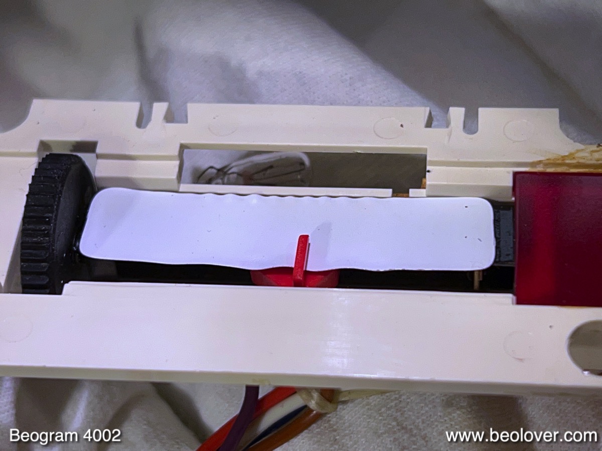
The slightly browned cover on the left side is the one that covers the 33 RPM light bulb. Most people use 33 RPM much more often than 45 RPM, and therefore the heat load from the light bulbs that illuminate the RPM indicators damages only the 33 RPM bulb cover over time. The 45 cover is usually pristine. Unfortunately, the heat from the bulb also damages the white plastic background of the indicator, i.e. when the cover is brown, one can assume that the background has also melted a bit from the heat. It usually gets wavy, which makes the background look uneven when the light is on. I removed the trimmer assembly and had a look, and indeed the white background on the left was wiggly:
Here it is shown magnified:
I removed both backgrounds, they are just white self-adhesive labels:
Then I replaced them with cut-to-size white 3M electrical tape:
I reinstalled the trimmer assembly and then replaced the light bulbs. This shows the original bulbs still installed, together with their Beolover LED replacements:
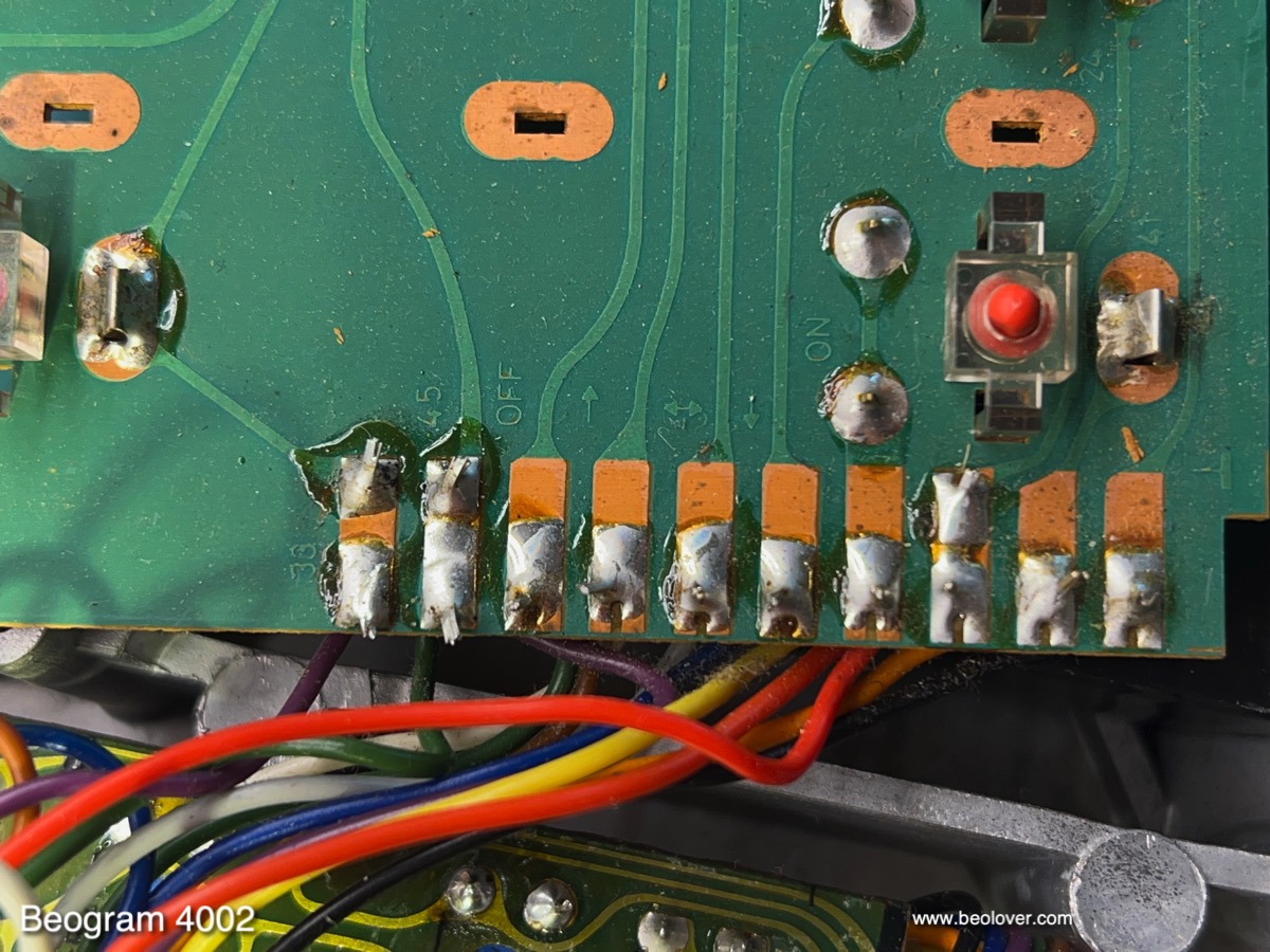
The LED assemblies solder directly to the pads that the bulbs are soldered to:
After replacing the covers:
The final LED went into the sensor arm. This shows the sensor compartment pulled out of the arm with the original bulb still installed. Next to it the Beolover LED assembly is shown:
After installation:
After this I focused on the output board. This shows the original setup:
I replaced the output relay and the capacitor that defines the time constant for activating the relay after arm lowering:
The next step was rebuilding the reservoir and motor capacitor section. This shows the Beolover capacitor assembly in place. At this moment I also installed the re-assembled motor, since it solders directly to the capacitor terminals:
While the main PCB and the keypad were still up, it was a good moment for replacing the disintegrated transport lock bushings. This shows one of them, which had completely fallen apart:
This shows the 3D printed Beolover replacement bushings. They come in two parts, which makes installation very simple:
Just put one half in from the bottom, and the other from the top and that is it:
This shows the bushing after re-assembling the lock:
This Beogram 4002 also had cracked plinth guiding washers:
I replaced them with 3D printed replicas. This shows a black one, like I install them up front so they are not visible:
Now it was time to put the deck back together and start doing all the adjustments and tests. This shows the adjustment process of the sensor arm transistor bias. It needs to be adjusted to achieve a 4V collector voltage:
After installing the biasing trimmer on the components side and bolting the board back in, I measured the sensor response to an empty platter. This shows the collector voltage of the sensor transistor. Each dip represents the passing of a platter rib beneath the sensor. The amplitude of more than 6V is more than enough to safely trigger disabling of the arm lowering function:
After this I set out to do the platter and floating chassis adjustments. But when I tried to put the big aluminum plate on, I realized that it collided with the motor pulley. This was a first, and initially there was a bit of head scratching!
Then I realized that the motor shaft was a bit too long on the pulley side, causing the pulley to stick up about 1.5 mm too high, and that is all it takes to have a conflict with the aluminum platter. Due to the elegant flatness of the Beogram design, there is not much space, and so the tolerances are pretty tight.
I removed the motor and I realized that indeed the shaft was not in the right position. This shows the motor bottom side, where the shaft is too far inside:
I think the shaft must have been pulled out a bit when I pried the pulley off.
I compared with an original motor I have on the shelf, and this is how it is supposed to look like:
I took the motor apart again, and used a small vise to carefully push the shaft 1.5 mm back into the rotor:
Then I re-installed the motor and I measured the motor signal, which came out to be a perfect sine wave, as it should be:
Now the aluminum plates fit again, and I did all the adjustments of platter/arm parallelism, arm height, floating chassis position etc...Once all this was done, I looked into the calibration of the tracking weight. the first step is always to replace the flimsy circlip that holds the counterweight adjustment screw in place
with a square nut:
This allows to bolt the counterweight solidly into place after calibrating the weight scale. That way the calibration survives shipping. Then I calibrated the weight scale on the adjustment wheel to be about right at the usual 1.2g weight that most B&O cartridges seem to need:
It is always best to adjust the weight with a digital scale. The adjustment wheel is notorious for being a bit off, and should therefore only be used in absence of a proper scale.
I also adjusted the arm lowering limit, which is an important insurance policy against tip damage if the arm should ever get lowered onto an empty platter due to a circuit malfunction:
The final adjustment was the tracking feedback:
The next step was to run a 24 hrs RPM stability test to make sure everything was o.k. with the platter drive. I hooked up my BeoloverRPM device, which allows logging the RPM for extended periods of time:
This is the curve I measured after ~24 hrs:
This is as good as it gets! The AC platter motors are very constant and there are only very rarely issues with them in terms of RPM stability!
I thought I was close to doing some first listening with this deck, and so I replaced the original, somewhat corroded DIN5 plug
with a nice gold plated modern all-metal unit:
After this I put a record on the platter.
The arm lowered on the record, and the output relay opened up. A loud hum came out of the speakers, but no music! This stumped me a bit, since the original DIN5 seemed unadulterated, and I copied the wiring pattern over 1:1 to the new plug, as usual. I measured continuity between the terminal on the cartridge tab and the DIN5 pins, and there was no continuity! Very strange!
I finally looked at the round connector that connected the output cable to the PCB, and it dawned on me that the front and left channels were reversed on the plug! There it is, that human creativity!!...;-)
I restored the wiring:
And then it was finally really time for a test spin! I selected one of my favorite Stanley Turrentine records that he recorded for the CTI label in 1973: "Don't Mess with Mr. T." (
CTI 6030).
Of course, this record was thoroughly cleaned on a CleanerVinyl ProXL System combined with a UC-3360 multi-frequency ultrasonic cleaner before listening. This restored the sound of this record to its original glory:Very beolovely! I hope I will soon get the redesigned Beolover AC-motor compatible RIAA pre-amplifier board from the manufacturer, and if it works as intended, this Beogram 5504 type will be the first one to receive it! It will also get the Beolover Commander remote control, which also comes in an
AC motor compatible 'flavor'. Stay tuned!




.jpg)




.jpg)


