Featured Post

Beolover SyncDrive: DC Platter Motor Replacement for Beogram 4002 and 4004 (Type 551x and 552x)

Late Beogram 4002 and the 4004 (Types 551x and 552x), which have DC platter motors instead of the earlier synchronous AC motors usually suff...

Showing posts with label 5502. Show all posts

Tuesday, April 11, 2023

Beogram 4002 (Type 5504): Installation of Newly Adapted Beolover RIAA Pre-Amp

After recently redesigning the Beolover internal RIAA pre-amplifier for DC-motor Beogram 4002/4 turntables, and adapting the circuit for the Beogram 4000, it was finally time for the next chapter in this design process: Adaptation of the circuit for the AC motor Beogram 4002.

The owner of the 4002 (5504) that I just restored asked me to install the RIAA and so his Beogram will be the first AC-motor 4002 featuring a Beolover RIAA!

This shows the new board:

The input jack of the board connects to a replicated Beogram style plug via a multi-lead wiring harness. The output jack on the right matches the plug that is on the output cable of this type Beogram.
Due to the large footprint of the output jack, I decided to give this design bypass switches instead of the two completely separate signal paths via separate input and output jacks that I chose for the DC motor board. The switches allow connecting the Beogram to a standard Phono input without re-installing the original output board.
A look at the backside of the board reveals a separate grounding wire that allows connecting the board ground to the chassis of the turntable. This has shown in my experiments to help if there are any 50Hz hum issues (but in some cases it also causes hum, so this is something to be tried out in your particular setup):
Here is a look at the board next to the original board that I restored when I finished this turntable:
For installation of the Beolover RIAA board, all that is required is unplugging the board

and replacing it with the Beolover RIAA board:

The only difference is that the ground wire needs to be bolted to the 'cable clamp' bolt:
This shows the board after bolting the keypad back in:
It is designed that the control features are accessible with the keypad cluster installed. This allows setting the gain and switch between RIAA and non-amplified operational modes.


Friday, September 25, 2020

Beogram 4002 (5503): Unit Switches Immediately to 45 RPM After Pressing Start

The Beogram 4002 (5503) that I am currently restoring exhibited a strange phenomenon when I tested it the first time after rebuilding all its functional parts (more about this process in a subsequent post):

After pressing START the carriage began to move while it immediately switched to 45 RPM. Pressing the 33 key switched it back to 33 RPM, but only as long as the key was pressed.

This immediately suggested that either TR3 or TR2 had an issue. Let's have a look at the relevant section of the circuit diagram:


This is how the speed selection works:
The base of TR3 is connected to the collector of TR4, and the base of TR4 is connected to the collector of TR3. Resistors 5R1 and 5R2 act as pull-up resistors together with the light bulbs IL1/2. I guess the resistors were added to keep the deck working even if a bulb burned out.
This causes a flip-flop behavior: When the base of TR3 is shorted to ground via the 45 switch in the keypad or TR2 (that is activated by the carriage as it travels towards the set-down point for singles), TR3 is turned off for a moment, causing its collector to go high, which in turn pulls the base of TR4 up, and that drives the collector of TR4 to GND since TR4 turns on. This then keeps the base of TR3 permanently grounded and the deck is running at 45 RPM (via switching TR6 on which changes the oscillation frequency of the Wien Oscillator to drive the AC motor at a higher RPM).
The opposite happens when the 33 key is pressed. This causes TR4 to be off and TR3 on, and so TR5 is turned on running the oscillator at a lower frequency.

I removed TR3 and checked it with my transistor tester:

Apparently it had turned into a voltage divider!...;-).
I replaced TR3 with a generic BC547B and that fixed the issue.

Sunday, September 20, 2015

Beogram 4002: Replacing the Detector Arm Light Bulb, Discussion of the Circuit and Relevant Oscilloscope Traces

The Beogram 4002 that just arrived needed a new light bulb for the detector arm. I replaced it with a new one. While it is a fairly simple operation to exchange the bulb, it can be a bit tricky to get the deck working again if the new bulb is not in the correct location. I made a short video about the progress that shows how to implant the new bulb, and also discusses the adjustment of its position. The video also discusses the relevant parts of the circuit and shows key oscilloscope measurements on a working detector set-up:


Here are high res pics of the oscilloscope traces. This shows the  weak signal at the base of TR3 while the platter spins under the detector:

This shows the signal after amplification through TR3 at its collector:

The signal is now about 6Vp-p. I have seen values between 5 and 7V in different 4002/4 units. This shows a representative trace at this point for a light bulb that is not properly adjusted, i.e. does not put enough light under the sensor lens:

Note that the Vp-p is now less than 1.5V due to the reduced light intensity. This shows the resulting signal at the base of TR4 after it passes capacitor C16:

the signal is now 1Vp-p but at a 21V offset to pull TR4 down and turn it on. When it is turned on capacitor 18 charges up with a sawtooth in sync with the platter ribs as they pass by under the detector:
Finally, the charged capacitor pulls the base of TR6 up via R34 (1M) and with this the tone arm lowering circuit is deprived of voltage and the arm cannot be lowered anymore. What a lovely analog control system!


Saturday, June 6, 2015

Beolover Shapeways Store! - First Beogram 400x Parts Available

I recently ordered a couple of my Beogram 400x parts, the 'cabinet guiding washers' and the 'transport lock bushings' from Shapeways to check out the quality of their offerings. 

I just tested the parts in my Beogram 4002. They turned out to be spot on and they fit extremely well. Furthermore, the parts are absolutely conform with the 3D CAD model: Their laser sintering process does not need supports for printing the parts, i.e. there are no more ugly support attachment points that need to be broken off or sanded away.

The parts are now offered at the 'Beolover Shapeways Store'. They print them on demand and ship them directly to the customer. A pretty neat business model, but it is not cheap and may take about 1-2 weeks until they ship. So, it is not the 'replicator' from Star Trek (yet), but it is definitely going there..."Earl grey-hot", anyone...;-)

Some impressions of the parts. They were manufactured in "White Strong Plastic". The store offers them in other materials, too, but they were not tested by me. I expect that at least the 'Black Strong Plastic' will come out as the white material. They are essentially the same polymer.

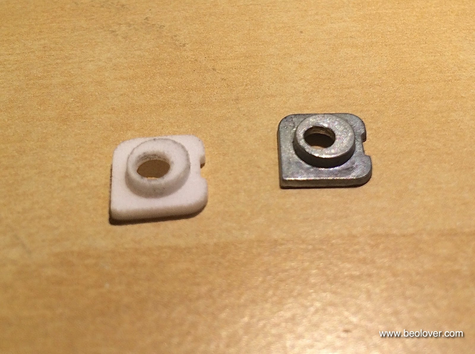
Cabinet guiding washer:

Comparison with original metal 'master' from my Beogram 4004:

The white one is the one that I installed. It looks a bit blackened at the rims since I took this picture after trying it out...(wasn't able to restrain myself from immediately putting it in after I excitedly ripped open the package...;-). An earlier video showing the part printed via laser lithography and about installing them is on YouTube.

These pictures show the transport lock bushings. One needs two per lock:


It is really amazing how well they fit...Shapeways has an incredible resolution and precision with their laser based process. A glimpse of the future, for sure! Beolove in the new millennium...;-). A video showing the installation process (and the original laser lithography parts) is on YouTube.


Monday, June 1, 2015

Beogram 4002: Awesome Refurbished Keypads in the House!

Today, I received a small package from Denmark containing two refurbished Beogram 4002 keypads.  As my beofriend put it 'the weather was right' for the paint job, and it appears he was right! Here is a picture of these beauties:


He is an absolute artist! They really look like they just rolled off the B&O line in 1975! Wonderful job! I sent him the worn out keypad of a recent Beogram 4002 restoration that I did, and then he found an additional one! I just wanted to have them available for my next 4002 restorations. I'll be happy to get you in touch with my friend if you would like to send him your keypad. Don't try this at home! This needs the "Master's Touch"!...;-)


Thursday, December 18, 2014

Beogram 4002/4004: Rebuilt Keypad Surface

A good day in beolover's life! I received a rebuilt Beogram 4002 keypad from a fellow 'beofriend' in Denmark. He is able to refinish the keypad surfaces to the original splendor. I was absolutely amazed when I received the package. The resurfaced switches looked 99% like the original. Very awesome! This will give the 4002 that I am restoring a pristine look. Well worth the money!

Here are a couple pictures. The first one shows the old pad with the circuit board removed for exchange to the rebuilt one. The usual damage to the keys from pressing on the surfaces with bare fingers is clearly apparent. Skin acids in combination with mechanical abrasion eats the surface finish over time, and a smudged appearance occurs. If you look closely, on the start key the finish is fully gone in a few spots. Absolutely un-beolovely!


Below is the rebuilt keypad. Absolutely pristine looking. If you hold it next to the damaged one, the pads have very much the same appearance. I am stunned! Like I time machined back to 1975 and picked one up at the B&O store! Excellent job! 


Wednesday, December 17, 2014

Beogram 4002/4004: 3D Printed Cabinet Guiding Washers

I am getting closer to finishing up my Beogram 4002. One of the still remaining annoying issues was the loose cabinet, which would not remain in its locked position due to the absence of the guiding washers that hold it in place. In the 4002 these washers were made from plexiglass, which easily cracks during the rigors of transport or just due to old age.
I opened up my Beogram 4004 to see how things look inside there, and it turns out that the 4004 has metal parts instead of the plexiglass ones in the 4002. I took measurements of one of those washers, and printed replacements on a Formlabs Form 1 stereolithography printer.

Here is a picture of the results: 


I also made a short video to demonstrate the functionality of the guiding washers:


The video shows that the new washers perform well. They are a bit elastic since the stereolithography printer plastic appears to be that way, so one needs to be a bit careful to not over tighten the screws when installing them. Otherwise, I was quite happy with the result. The cabinet slides snugly in its tracks.

Wednesday, December 10, 2014

Beogram 4002/4004: Replacement of the Transport Lock Bushings With 3D Printed Parts

I recently got into 3D printing with stereo lithography. This proved a valuable skill for replacing the decayed rubber bushings in the transport locks of my Beogram 4002. Here is a picture of how I found these bushings upon opening the Beogram up:


Clearly the rubber had seen better times. So I removed the fragments and designed a two-part replacement solution with Autodesk Inventor that could be conveniently installed without having to extract the floating turntable chassis. I printed the parts with a Form 1 stereo lithography (SLA) 3D printer, which produces relatively soft and pliable parts, ideal for the task of dampening impact during transport of a precious Beogram! Here is the result of my labor:


The 10-15 micron resolution of these SLA printers is much superior to filament based printers (~100 microns), i.e. it is a much better technology for small parts that need to have an exact fit. In this case, the fit needed to be pretty good to be able to generate a press-fit, that would hold both halves of the bushing in the opening in the chassis. This worked very nicely as you can see in this video, where I demonstrate the installation. Enjoy!:


Thursday, December 4, 2014

Beogram 4002/4004: Speed Selector Circuit and Replacement of Its Incandescent Light Bulbs with LEDs

The last incandescent light bulbs are now gone in my Beogram 4002. I decided to completely replace all light bulbs since I like the longterm stability of LEDs. Furthermore, with red-green LEDs one can achieve a very authentic incandescent feel (much better than with single-color yellow or amber LEDs). I made a video about the process. The video also explores the speed selector circuit and it shows the relevant circuit diagram sections. Here it is:


Here are a few pictures of the LEDs after installation, and the look of the scales with LED illumination (for comparison - the insert in the video title shows an amber LED, which did not produce a satisfactory outcome - more in the video):


Sunday, November 30, 2014

Beogram 4002/4004: New Belts and RPM Adjustment

A few months ago I received new Beogram 4002/4004 belts from 'Dillen' (Beoworld.org). Now was finally the time to install them into the Beogram 4002 that I am currently restoring. It seemed to need a new drive belt, since I had to considerably increase the speed trimmer to achieve 33 RPM. The Servo Belt also showed cracks. It seems it may have still been original. It had the prescribed triangular crossection, matching the groove in the pulley that drives the carriage spindle.

As in the case of the Beocord 5000, I thought it useful to take some measurements of the old and new belts for future reference (like when diving archeologists bring up this turntable in the year 2358 from the ocean floor where Florida used to be before global warming...;-):

Belt
Old ID
New ID
Old Crossection
New Crossection
Drive Belt (flat belt)
17” length when pressed flat
Width: 5 mm
/0.2”
Thickn.: 0.5 mm
0.020”
Width: 5 mm
/0.2”
Thickn.: 0.85mm/
0.033”
Servo Belt
31 mm
/1.2”
31.5 mm
/1.23”
Triangular
Height: 1.5 mm /0.059”
Base: 2 mm /0.078”
Square
0.75 mm/0.030”

I really like the much tauter feel of the new, thicker, flat belt...and indeed, after I put the new drive belt in, the speed was considerably higher, indicating slippage with the old belt. Now the speed trimmer was much closer to the '0' mark for a precise 33 RPM, i.e. the slippage was much less. I decided to make this perfect, and adjusted the primary speed trimmers on the circuit board (R14 for 45 RMP and R15 for 33 RPM) for a correct RPM setting when the user accessible trimmers are set to '0'. I did this with a small all-metal watch maker screwdriver for 33 RPM while holding down the '33' key (as one does for sweeping the platter before starting to play a record). There I noticed a remarkable behavior: The speed of the platter would immediately increase, seemingly beyond 45 RPM, whenever I stuck the screwdriver into the slot of the trimmer. After extracting it the speed would normalize...it appears that my body's resistance path to GND via the key pad affected the time constant formed with C3, which then throws off the difference amplifier in IC3, resulting in a change of speed of the motor.

Lesson learned: Finally get rid of the all-metal screwdrivers...they got me in trouble before when I fried one of the outputs of my Beomaster 6000 4-Channel by a screwdriver-caused short when adjusting the quiescent current...;-).

Saturday, November 29, 2014

Beogram 4004/4002: Tracking Force Adjustment and Zero Force Balancing

I noticed that the Beogram 4002 that I am currently fixing up needed a tracking force setting of 1.5g to produce an acceptable undistorted signal with its MMC20EN cartridge. At 1g the signal would be completely distorted. A clear sign that something was wrong with the tracking force adjustment (the cartridge works well on my Beogram 4004...).

It turned out that the arm needed a zero force rebalancing. The counter weight in the back of the tone arm was way too far back. I made a video about the procedure. The video shows how to do the zero force adjustment, and then how to use the tracking force gauge that comes with B&O cartridges to get a precise adjustment of the tracking weight:


It is interesting to note that the scale on the adjustment bushing at the back of the cartridge appears to be only a rough estimate of the weight acting on the needle. In my opinion, this is not surprising considering the design of the mechanism using a variable torsion spring to press the arm down.

There is another issue with this mechanism: The adjustment screw is only held in place at the back plate with a retaining clip, which gives the counter weight 0.5-1 mm play along the arm axis. This, of course, can throw off the zero balance when the turntable is moved after an adjustment. I fixed this in Beogram 4004 with a M3 counter nut and a washer. Since the nut needs to be tightened after the adjustment the weight position changes slightly once the nut is tightened. This requires multiple attempts to get it right, but I think this is worth the effort, since this will lock the adjustment in place for long-term stability. Here is a photo of the installed nut and washer:


Friday, November 28, 2014

Beogram 4004: Characterizing a MMC20EN Cartridge with an Analogue Productions Test LP

I recently bought 'The Ultimate Analogue Test LP' from Analogue Productions. I felt I needed to be able to characterize the output of my cartridges and I read about this LP. It is a heavy duty 180g high-quality vinyl that has all the relevant test tracks for basic measurements.

I connected the oscilloscope to the DIN5 connector via a DIN-to-RCA breakout and two RCA-BNC adapters. This allowed me to form a shielded signal path from the output of the Beogram 4004 to the oscilloscope. However, the measurement was still pretty noisy, so I resorted to using a low pass coupling for the trigger and averaging. This gave me usable traces. Here is a shot of the oscilloscope screen on the 1 kHz test track:


It is obvious that the MMC20EN cartridge that came with my Beogram 4002 puts out a well balanced signal on both channels. The peak to peak amplitude of the 1 kHz signal is about 15 mV. This also seems to be a pretty good way to calibrate the RPM of the platter...

Here is a shot of the 100 Hz track (timebase is 10 ms/sq):


As expected the amplitude is considerably lower (maybe 4 mV without the noise) than for the 1 kHz signal due to the RIAA pre-emphasis. This is necessary at low frequencies to keep the groove width reasonable (Faraday's law prescribes that the induced EMF is proportional to the change of the magnetic field, which in turn is proportional to the velocity of the moving magnet, iron or coil in a cartridge). I found an excellent summary that explains the background behind the RIAA curve and the historic path towards it. The article is by Gary A. Galo and can be found here.

In short, the RIAA curve lowers the amplitude progressively towards lower frequencies to reduce the groove width (otherwise long playing records would not be possible). At high frequencies the amplitude is increased to stay ahead of the noise, which, due to its high frequency content is an effective EMF generator. Hence the signal amplitude needs to be a few magnitudes larger than the noise amplitude, that in the amplifier signal + noise can be reduced together, thereby reducing the noise relative to the original signal level. This is a similar approach as is used in Dolby noise reduction systems. 

The 10 kHz track on the Analogue Productions LP produces a standardized -20 dB amplitude (i.e. 10x smaller than the other two tracks, which are at 0 dB. 0 dB apparently corresponds to a 7 cm/s stylus velocity, as suggested on the LP sleeve. Here is the (pretty noisy, disregard the Freq measurement indicator) measurement (timebase is 100 us/sq):


Without the noise the amplitude might be about 10 mV or so, i.e. it were at about 100 mV at 0 dB. That would give us about a factor 7 relative to the 1 kHz signal. 20*log(7)=16.9 dB, which, considering the noisy measurement, is reasonably close to the RIAA curve (from stereophile.com, the blue curve is the curve used on records, the red one is an idealized 6 dB/octave curve, which would be best, but cannot be implemented due to practical reasons), which suggests a pre-emphasis of about 13 dB at 10 kHz:


The 100 Hz measured amplitude above is also reasonably close to the curve: 20*log(4/15)= -11.5 dB (compared to about -13 on the curve....

All in all another interesting evening at Beolover's lab...;-)


Tuesday, November 25, 2014

Beogram 4002: Signal Path between DIN5 Plug and Cartridge, Plug Replacement

I finally wanted to try out the Beogram 4002 that I am getting ready for the 21st century. While everything seems to work now, the DIN 5 plug looked really bad. Rusty and bent...so I decided to replace it with a modern quality plug (Neutrik AG Rean NYS 322G) with gold plated pins to ensure lasting contact at my Beomaster 6000 Aux input. Here is a pic of the old plug...pretty ugly! Not sure what the previous owner was up to...:


Before I soldered the new plug on, I noted the signal path down to ensure that I would make the right connections after cutting off the old plug. Here is a schematic of my measurements (note that the cartridge connectors are shown on a mirror that I held below the arm):


It is interesting to note that the cartridge is essentially directly connected to the amplifier with the recommended 'star arrangement' ground (all ground connections come together at one central point and loops are avoided). The Beogram has its ground connected to the chassis, which could cause a ground loop if it were connected to the phono preamp ground and there were a conductive connection between the Beogram chassis and earth (usually the Beogram chassis floats due to the isolating feet and the absence of a earth connector at the standard two-prong power entry). The shield of the cable, however, is connected to the chassis, and will make a direct connection to the amplifier chassis, i.e. in the end the Beogram ground is connected to the amplifier ground. But this should be o.k due to the star-arrangement, even if there is a potential difference between the two units. And indeed, I was not able to discern any hum from the speakers after hooking the Beogram up.
Another interesting detail is that the back channel connections are fed to the plug, even in a 2-channel Beogram 4002 or 4004. I guess, when these decks were new, the CD4 upgrade was available for an easy plug-in at the Bang & Olufsen dealerships. Sometimes, I wish I had a time machine!...;-)

Here are a few pics from the plug replacement procedure. This was actually not trivial due to the heavy duty double shielded cable, which required a few sweat producing manipulations of the 22 gauge leads that carry the signal, while soldering on the heavy duty shield and signal GND connection:


And here the final result: 


Just hooked the Beogram to my Beomaster 6000, and it sounds beautiful! Andrew Hill: Dance with Death on an original 1970s Blue Note pressing. Fantastic!

Thursday, November 20, 2014

Beogram 4002: Replacing the Detector Arm Light Bulb with a LED

The Beogram 4002 that I am currently rebuilding also needed a new light bulb in the detector arm. The previous owner had done a poorly executed 'repair' attempt, and ripped out two wires from the detector arm lamp assembly, while also bending the photo cell backwards - unbelievable what some 'experts' are coming up with. Here is a picture of the assembly as I saw it the first time:


For comparison I pulled the compartment out of the detector arm of my Beogram 4004, which is in a pretty good condition:


These light bulbs are hard to come by and I also believe in LEDs as a way to get these units stable for another 30 years. So I decided to replace the light bulb with a small 3 mm LED.

This effort turned into an interesting experience, since on first try, I was not able to get the record detection mechanism working after I put in the LED with a 220 Ohm resistor. The turn table simply ignored any record that I would put on its platter.

Study of the circuit revealed that the original designers of this gorgeous piece of analog control electronics proofed the circuit against failing light bulbs (a failed light bulb would result in always detecting a record whether there is one or not, with potentially fatal consequences for the pickup). The much lower current in the LED resulted in a partial activation of this fail safe mechanism, which prevented the Beogram from auto-lowering its arm. This was fixed by replacing R36 with a 560 Ohm resistor, which resorted the original balance in the circuit.

I made a video about the entire process. The video discusses the detector arm circuit and explains how the LED exchange was performed:


Here is a photo of the final result:


Thursday, November 13, 2014

Beogram 4002: Conversion of the Tracking Sensor Light Bulb to an LED and Adjustment of the Sensor

I started working on a Beogram 4002 that I obtained locally from Craigslist about a year ago. I thought it would be a nice practice run before I give the cherished Beogram 6000 4-Channel a go that I recently found.

I plugged it in after opening it up in the hope to see the location of the smoke should any develop...;-). No smoke, but no tracking either. Pretty much nothing worked, no tone arm lowering etc...also some traces of amateur repairs.

I determined that the light bulb in the tracking sensor was out, and I decided to replace it with an LED since the bulb cannot easily be replaced since it is glued into the sensor housing, i.e. cannot be separated. I also am a fan of LEDs since they have a much better long-term stability, especially should the unit be shipped at some point.

I ended up using a 3D printed part to hold the LED and the current limiting resistor. The part essentially replaced the light bulb fixture on the sensor housing. Here is a picture of the end result:


I made a video that explains the whole procedure including the adjustment of the tracking mechanism for the right tone arm angle relative to the record grooves. The video also discusses how the tracking mechanism works. Enjoy!:


On to the dead sensor arm!