Featured Post

Beolover SyncDrive: DC Platter Motor Replacement for Beogram 4002 and 4004 (Type 551x and 552x)

Late Beogram 4002 and the 4004 (Types 551x and 552x), which have DC platter motors instead of the earlier synchronous AC motors usually suff...

Showing posts with label 78SSBG4002. Show all posts

Monday, March 21, 2016

Beogram 4002 (5513): Infusing Oilite Brass Bearings of DC Motor with Oil Under Vacuum

One of the challenges with restoring DC motor Beogram 4002/4 Types (551x and 552x) is the restoration of the motor itself. Most of the DC motors present themselves with loud running noise and/or strong RPM variations at this point in time. It turns out that simply taking the motor apart and lubricating the brass sleeve bearings with grease is only a temporary solution.
The bearings used in these motors are 'oilite' brass bearings (see a recent thread on Beoworld where Dillen hinted at this). Such bearings are infused with oil after manufacturing. The brass is porous, and therefore oil can be 'inserted' into the metal itself via a vacuum based infusion process. This results in light duty bearings that can run without the need for external lubrication. However, over time the oil is slowly depleted from the bearing metal (and probably distributed inside the motor). Once the oil is gone and the bearing dry the noise issues and RPM variations start occurring.
The restoration of the bearings requires to infuse fresh oil into the metal. Unfortunately, one has to completely disassemble the motor to get to the bearings (one can force them out without disassembly, but it is impossible to get them back in...).

Here are a few impressions of the process. This shows the motor disassembled:
The two bearings are actually different:
The bottom bearing is shown right with its plastic support washer next to it. The top bearing is on the left. It is slightly bigger.
The infusion process can be done with SAE 30 motor oil and one needs to pull a vacuum in order to suck the air out of the pores of the brass volume to make room for the oil that it can diffuse in by means of Brown's motion. I did this with a FoodSaver vacuum sealer unit that came with an attachment for Ball mason jars. Here is an impression of the bearings in the oil under vacuum in the jar:
As soon as the vacuum is applied small air bubbles arise from the bearings. They accumulate on the surface of the oil as seen in the photo. It is interesting to note that the top bearing produced considerably more bubbles than the bottom one. This is probably a result of the higher friction seen by the top bearing due to the belt torque applied to it. After about six hours the bubbling pretty much stops and the bearings are ready for re-installation.
This is where it gets a bit difficult since the top bearing is held in place with a metal ring that is fixed in place with tabs that needed to be bent up to get the bearing out. It can be difficult to get the tabs bent back far enough to ensure a snug fit of the bearing in its fixture.

I designed a 3D printed tool to simplify this process:
The red cylinder goes inside the motor housing to hold the ring in place:
Once the ring is pushed up all the way the tabs can be bend slightly with pliers:
the final press fit of the tabs into the small recesses is then done with the top part of the tool and adjustable pliers against the red bottom part:
This results is a pretty tight fit almost as good as before disassembly:
I am planning to make a video about this process. But for now it is time to test this motor for 24 hrs using my BeoloverRPM device:
33.33! So far so good! Let's see how this motor feels about things tomorrow!


Wednesday, November 18, 2015

Beogram 4002/4004: Adjusting the Tonearm Lowering Limit

While the Beogram 4002 that I currently restored has safely returned to its owner I still owed a report on the final tonearm adjustments. Beolover blogs all tasks that are performed during a restoration! So here it is as promised:

An important adjustment on the tonearm assembly is the arm lowering limit. This limit prevents the needle from hitting the platter ribs in case the photosensor in the sensor arm fails. The electronic control circuitry has no way to detect this issue and prevent the arm from lowering. If the sensor fails the system will interpret it as 'record present' and lower the arm. This is the main reason why B&O came up with the lower platter rib areas, which are located at the touch down points for LPs and singles. This allows giving the arm a lowering limit that can be below the surface of the record, while still prevent the stylus from being shaved off by a rib should it ever touch down without a record present.

I made a short video about this important adjustment:


After I did this adjustment, I also adjusted the zero weight of the arm (see here for a video how to do this) and installed a nut and a washer to replace the original retaining washer that keeps the counterweight adjustment screw in the assembly. Unfortunately this washer results in a lot of play in the mechanism, which can result in a change of the zero force adjustment during shipping and set-up, i.e. is not acceptable for a Beolover restoration! Here are a couple of pictures showing the original setup,

and the modified one:
All good now in the back of the tonearm assembly!

Sunday, November 8, 2015

Beogram 4002 (5513): Installation of a New Output Relay and a GND Switch

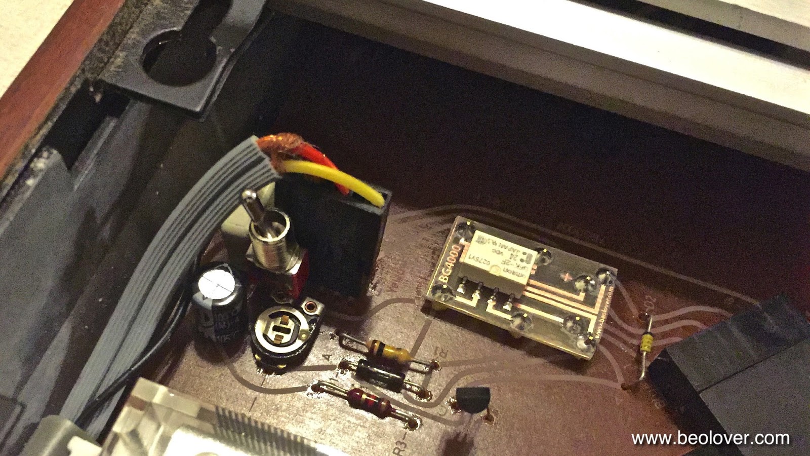
While I was testing the Beogram 4002 (5513) that I restored in recent weeks I realized that the output relay once in a while would not open up after the tip touched down, hence, preventing the audio signal from reaching the amplifier. Luckily the relay is the same type that is used for RPM switching in both 4002 and 4000 models. Therefore, I was able to use the breakout board that I recently developed for replacing the RPM relay in a Beogram 4000 with a modern encapsulated SMD signal relay.

While I installed the new relay I took the opportunity to also install a switch on this board that allows to tie signal and system grounds to deal with humming problems if necessary. Depending how the amplifier is setup it can become advantageous to tie the two grounds together to prevent the formation of grounding loops and/or open leads that can introduce ambient EMI into the sensitive phono preamp input. 

This shows the original relay:

And after installing the SMD replacement and the switch: 

This shows the board after installing it in the Beogram and replacing the plug that connects the cable:


Beogram 4002: Polishing the Hood

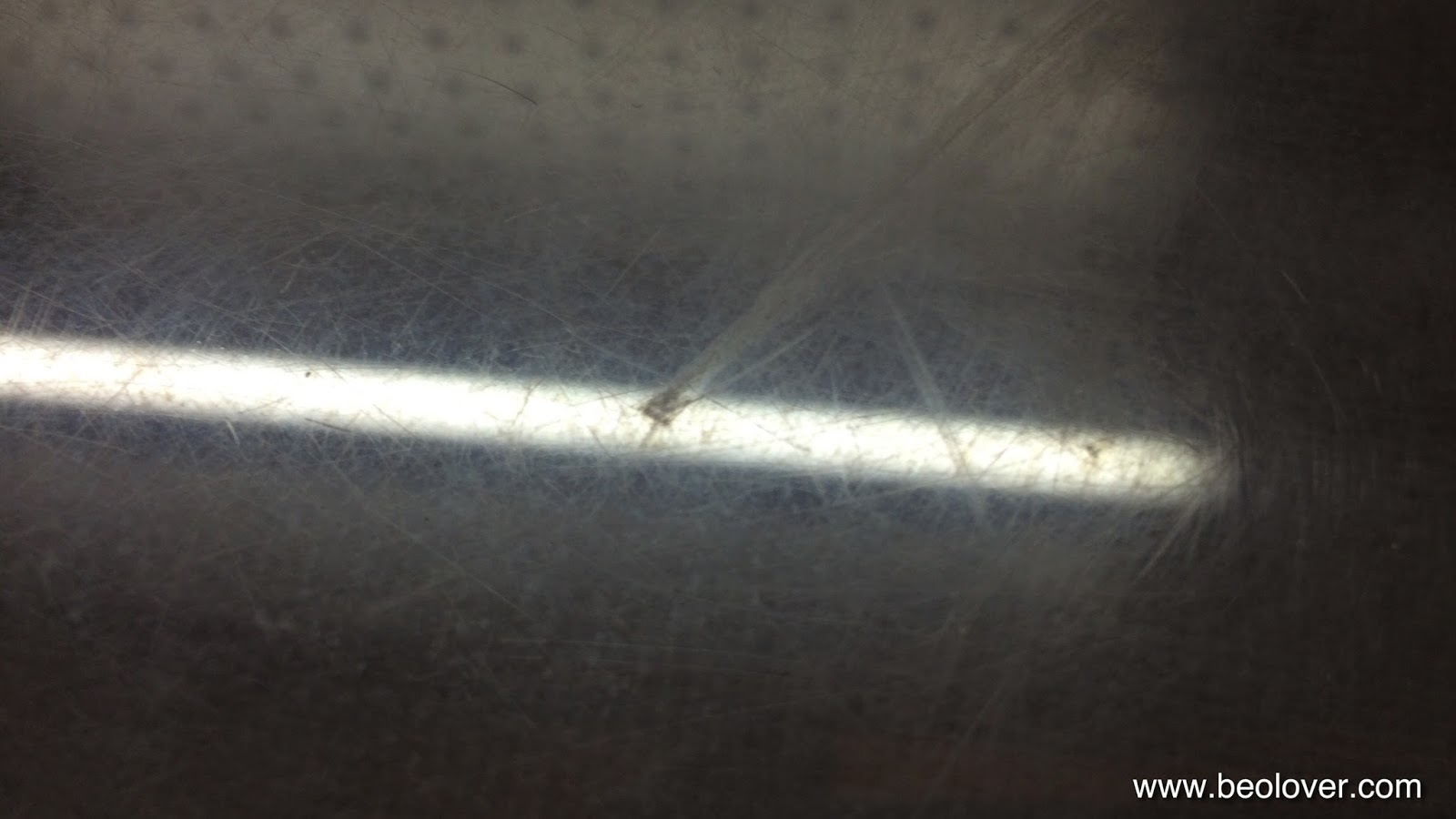
The beautification of the 4002 that I am rebuilding continues. Today was hood polishing day...always a nice workout, probably the equivalent of 100 push-ups...(but only for one arm...;-). This plexiglass hood had some significant scratches:

So I started out as usual with 200 grit dry paper to equalize the surface:
And then gradually rebuilt the polish with Micromesh polishing cloth:


And the final step with Micromesh Micro-Gloss:

Saturday, November 7, 2015

Beogram 4002: Replacement of Rusty RCA Plugs

Today I replaced the old grimy and rusty RCA plugs on the Beogram 4002 (5513) that I am finishing up right now. Here is a picture of the old plugs:


I used some nice heavy duty Amphenol gold plated RCA plugs that will do a fine job transmitting the low voltage MMC signal to the amplifier. These plugs are nice since their housing is metal, which improves their shielding properties to keep the signal path insulated from the EM environment. Here is a picture after soldering them on:

And closed up:

Pretty, aren't they??


Thursday, October 29, 2015

Beogram 4002 (5513): Sudden RPM Changes

I thought I was pretty much done with the Beogram 4002 (5513) that I recently restored and I started testing it by listening to my favorite vinyls. After a while I realized that the RPM drifted over time. This was cured by replacing the original RPM relay with a drop-in replacement based on a modern encapsulated signal relay and exchanging the original principal 5k RPM trimmers on the circuit board with modern encapsulated multi-turn precision trimmers. Here are a few impressions:
This shows the original RPM relay on the main PCB:
This relay is the same as used in the Beogram 4000, so my recent design of a replacement of the 4000 relay could be fitted here, too. This shows the drop-in replacement board:

And installed:
Above-left of the relay are the original 5k trimmers. I replaced them with these:


The lead-extensions were needed since I had to install them upside down to make sure that the set screws are accessible through the PCB from the solder side. Otherwise, it would be impossible to tune the RPM while the deck is running:
Here is a top-view:

This solved the RPM drift issue. However after a lot of listening to vinyls, most notably an original first pressing of a 12" single of Grace Jones' "Slave to the Rhythm", it became apparent that in addition to the drift phenomenon there was an other, more serious issue: Sudden sharp drops in RPM that would only occur on relatively rare but completely random occasions. Not so great! I decided to get to the bottom of this and I connect my oscilloscope to the signals around IC3 that controls the DC motor feedback control loop. To observe these signals while a record is playing one needs to solder jumper wires to the interesting signals of IC3:
This enabled to hook up my 4 channel oscilloscope:

Here are the traces that I measured during the occurrence of the phenomenon. Luckily once the issue started to happen it reoccurred a few times in a row, allowing me to capture traces with the single shot button. This shows the phenomenon at 33 RPM

and the much more frequently occurring analog at 45 RPM:

The traces are assigned as follows (see circuit diagram below): blue pin 1 (this is the AC induction signal from the DC motor feedback coils), yellow: pin 6 (this is the pulse width modulated output from the Schmitt trigger that corresponds to the amount of power the motor receives, green pin 7 (this is the RC network that determines the actual pulse width that the Schmitt trigger puts out, and red pin 4 (this voltage relative to the TR2 stabilized 8.5V output corresponds to the voltage the motor receives).
All this was pretty interesting: The DC motor of the Beogram 4002 (5513) is a 3-pole motor. This means that each of the three coils on the rotor is fully powered up every six commutator contact changes (see here for some awesome animations and basic info). This suggests that the observed aberration in the pin 1 traces are related to one specific cycle of the motor rotation since the 'missing valley' phenomenon occurs every 6 wave cycles. So I took the motor apart again and throughly cleaned the commutator and the brushes and put it back together. This made the phenomenon much rarer but did not alleviate the issue completely. I may go ahead and put the motor of a parts unit in for now until I figure out how to fully fix this. The issue with intermittent problems is that they are intermittent. So it is difficult to make sure that a fix 'sticks'  100%. All this shows the principal issue with DC motors in turntables: They need a precisely working feedback mechanism to keep the RPM constant. All this is a non-issue with AC synchronous motors that simply 'obey' a sine wave that is fed into them. 


Monday, October 19, 2015

Beogram 4002 (5513): Installation of the Latest Version of the Beogram Commander Remote Control

On occasion of my latest Beogram 4002 (5513) restoration, I updated the Beogram 4002 Commander remote control that I developed earlier this year with a 'pairing' function, that eliminates potential conflicts between the Commander's Apple remote and pre-existing Apple TVs etc... I also added the ability to switch between 33 and 45 RPM remotely, thereby fully eliminating the need to use the keypad ever again (to protect it's fragile lacquer coating from skin acids etc...). I made a video about the latest version that explains the functions in detail, and also gives a demonstration of the remote functions as well as the pairing mechanism:


Here are a few impressions of the Commander board as it was installed in the Beogram 4002. This shows the Commander board including its 3D printed tray and mounting 'plug'. The board plugs directly into the keypad connector on the main PCB of the Beogram. The mounting plug enables reusing of the original PCB mounting screw that is located beneath the board to safely fix the Commander board into place once it is plugged in:

This shows the board installed. The keyboard connector is plugged into the white on-board connector and routed through to the original connector on the main PCB. This ensures continued functionality of the keyboard with the Commander installed.


Thursday, October 8, 2015

Beogram 4002 (5513): Adjusting the Floating Chassis Height

Once the main platter bearing is adjusted in a Beogram 4002 (5513), the floating chassis height needs to be set in a way that the aluminum surface of the platter is flush with the surrounding aluminum panels. This adjustment is done by turning the nuts that define the height of the leaf springs that keep the chassis suspended for vibration insulation. This is best done with a 8 mm hex wrench bit:

Simply turn it CW to lift the chassis or CCW to lower it. This needs to be done repeatedly for all three of the springs until the platter is flush with the aluminum panels all around. I recently made a video that shows this process on a Beogram 4000. The difference here is that the 4002/4004 models do not have a counter nut, i.e.one should put a dab of paint on the nuts to lock them in place once the adjustment is satisfactory. If the platter is not centered in the aluminum panel (do this with the belt in place) then the position of the chassis can be set by bending the threaded rods on which the nuts sit. This is a bit a dicey operation where some relatively brute force needs to be applied with high precision. Nothing for the faint of heart!

This shows the end result. The platter is fully flush and looks just gorgeous!:

Here another angle showing off the lovely restored keypad:

Aren't they beautiful, these babies?? This is Beolove!


Wednesday, October 7, 2015

Beogram 4002 (5513): Restoration of Worn Keypad

I am approaching the detail&beautification stage of the Beogram 4002 (5513) restoration that I am currently doing. This Beogram has (like 90% of them) a worn keypad. The original coating simply is not up to the stresses presented by skin chemistry containing acids and fats. Usually at this age if the deck has seen even only moderate use the pads show ugly finger smudges. I recently had some pads refurbished by a beofriend in Denmark to have them on hand when needed for restorations (I'd be happy to get you in touch if you want to get your keypad rebuilt!)

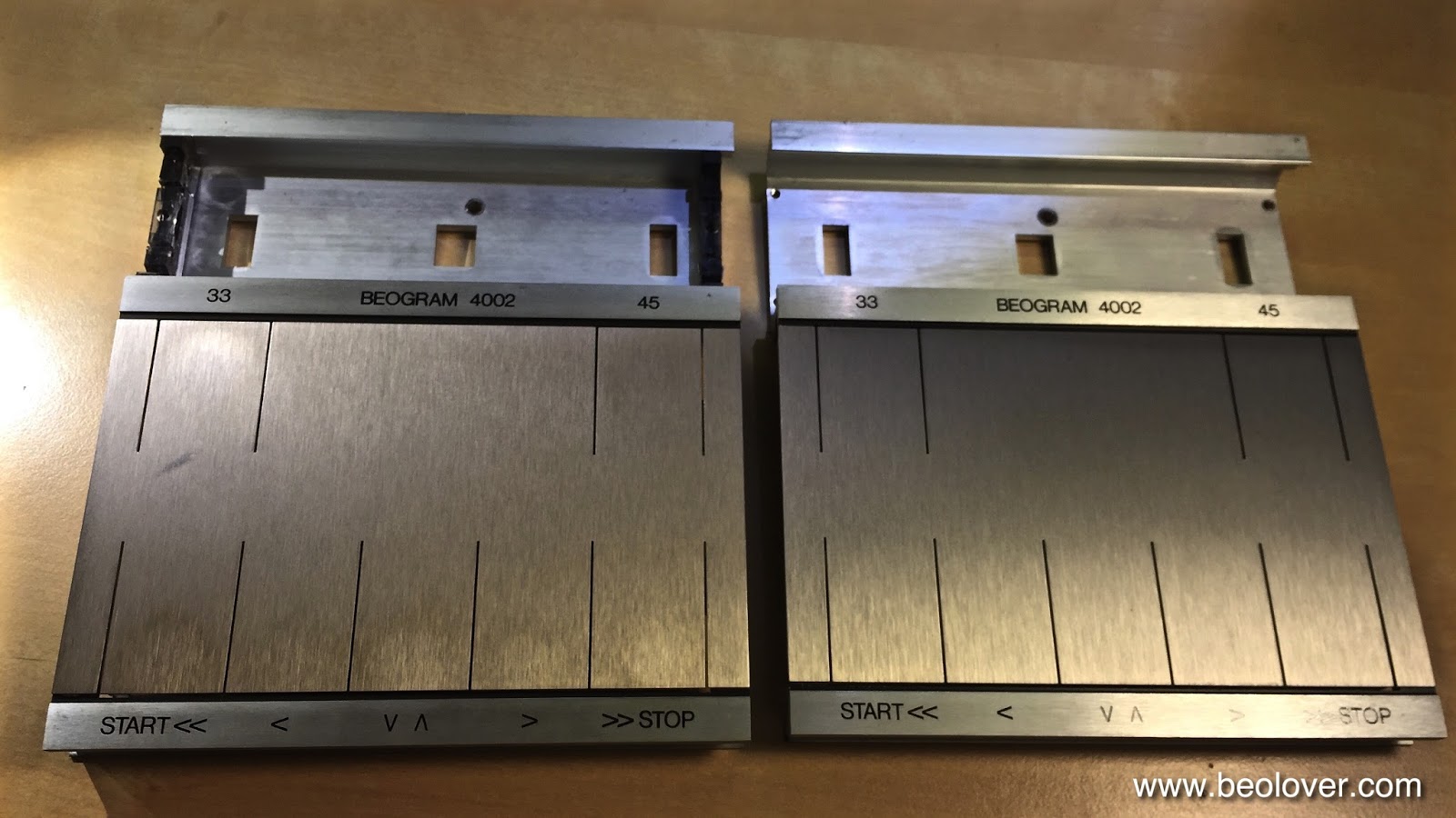
Here are a few impressions. This is the original worn keypad:

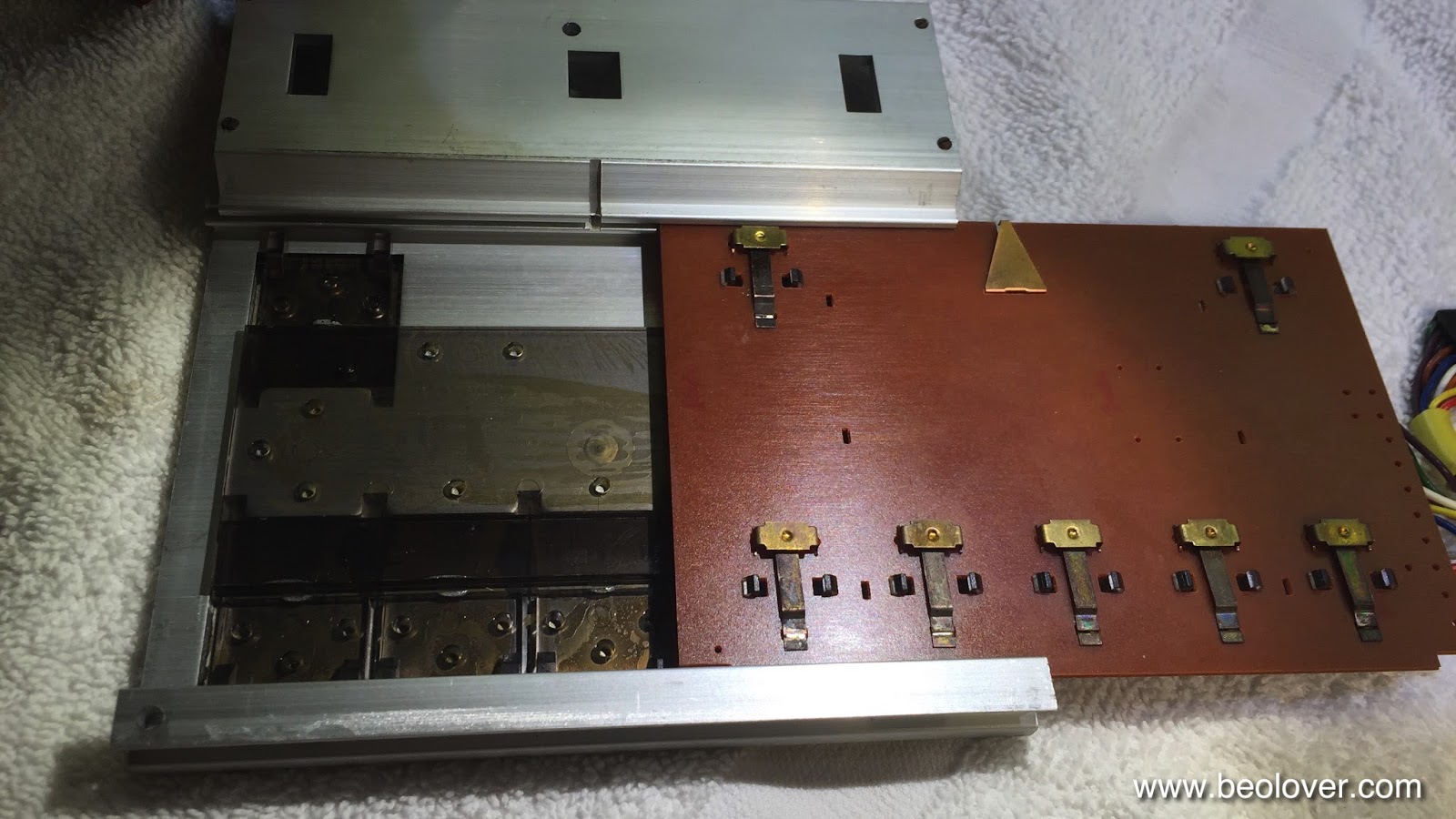
I needed to switch over the PCB that carries the actual switches, hence this was a good moment to refreshen the contact pads. I usually give them a light sanding with 2000 grit paper and then a coat of DeoxIT D100 to prevent further oxidation if they are not bent (if they are one needs to extract them, straighten them out and solder them back into place):

Then it was time to slide the PCB out of the original keypad:

Here is a comparison between old and rebuilt:
And after installation:

Doesn't my friend do an amazing job?? They really look very close to new! Like traveling with a time machine back to a B&O store in the 70s and picking one up!


Tuesday, October 6, 2015

Beogram 4002/4004: Replacement of a Broken Cable Clamp/PCB Holder

The Beogram 4002 (5513) that I am restoring right now had a cracked cable clamp/PCB holder that needed replacement. This gave me a chance to put a part file to work that a Beofriend from New Zealand sent me in exchange for at-cost access to my Shapeway Store parts. I recently had it manufactured at Shapeways since I wanted to test it before adding it to my store inventory. 

Here are a few pictures. This shows the broken clamp:

Here is the replacement part printed in white together with the original broken part:

And this shows it after installation. It makes a nice fit with the PCB and holds it tightly in place while giving the audio cable the support it needs to stay put:

After this successful test, I made the part available to other B&O enthusiasts at my store:


Beogram 4002/4004: Replacement of Decayed Transport Lock Bushings

About 50% of all Beogram 4002/4004s seem to have decayed transport lock bushings. A while back I developed a 3D printed replacement part that can be inserted without needing to disassemble the chassis. The part is available in my Shapeways store. Here is a picture of a set of three bushings (you will need 6 parts. Two make up one complete bushing (See below for a link to the installation video).


The Beogram 4002 (5513) that I am currently restoring also had this problem. When I took it out of the box, the telltale orange fragments were all over the place. So I replaced the fragmented bushings with my 3D printed replacements. Here are a few pictures of this effort taken while I worked on the lock next to the carriage servo motor.
This shows the orange fragments and the lock before I fixed it:

Here you see the remnants of the original lock as it crumbled out of the mounting hole:
After cleaning all the debris, I inserted the lower bushing part:
Then I added the top part:

And then put the lock screw in place together with the mounting plate:

This procedure needs to be done for all three transport locks. When I designed the part, I also made a short video about installing the bushings: