Featured Post

Beolover SyncDrive: DC Platter Motor Replacement for Beogram 4002 and 4004 (Type 551x and 552x)

Late Beogram 4002 and the 4004 (Types 551x and 552x), which have DC platter motors instead of the earlier synchronous AC motors usually suff...

Showing posts with label lubrication. Show all posts

Monday, August 3, 2026

Beogram 4002: Restoration of DC Platter Motor

I recently received a Beogram 4002 DC platter motor from a customer in France for restoration. His Beogram had the usual randomly occurring RPM variations. Something that will most likely be fixed by re-infusing the dry motor shaft bearings with oil under vacuum. Most of these motors have bearings that lost all of their stored oil, and this causes the shaft friction to increase significantly.

This shows the motor as received:

I disassembled it to extract the shaft bearings:

The bearings are the two small donuts upfront on the black pad. I submerged them in synthetic oil and pulled a vacuum. Immediately, strong bubbling started around the bearings:
The bubbling indicates that air is being drawn from the pores of the Oilite-bearing material. The leaving air is successively supplanted by oil in a diffusion process. The process has completed when the bubbling stops. In this case, this happened after about two days. At that point, I extracted the bearings from the vacuum chamber:
Then I reassembled the motor with a new Beolover DC Platter Motor Pulley for Beogram 4002 and 4004 and installed it in my bench Beogram 4002 for testing with the BeoloverRPM device:
The BeoloverRPM is able to log the RPM in 10s intervals into a serial port of a computer over long periods of time. This allows precise detection of intermittent RPM deviations that otherwise would be difficult to detect. This is the graph I measured after about 24 hrs:


This flat curve is 'as good as it gets' with Beogram DC platter motors! This motor is ready for duty again! It is time to send this motor home to France for another tour of duty in its Beogram 4002!


Saturday, April 19, 2025

Beogram 4002: DC Platter Motor Restoration

I recently received the DC platter motor of a Beogram 4002 from a customer in Ohio. The deck showed the usual RPM variations indicative of dry motor bearings.

This shows the motor as received:

I disassembled the motor to extract the bearings:
The bearings are the two small donuts on the black pad. I immersed them in synthetic oil and pulled a vacuum. Immediately bubbling started around the bearings:
The bubbles represent air being drawn from the porous Oilite material. As the air leaves the bearings fresh oil can diffuse into the evacuated pores. The process took about 2 days until the bubbling stopped.
I reassembled the motor and then it was time for a 24 hrs RPM stability measurement with the BeoloverRPM device. It is able to log the RPM every 10 seconds into a serial port of a computer. This shows the BeoloverRPM in action:
This is the data I collected over 24 hrs:
There is still a degree of slow long-term RPM variations. These should go away after playing a number of records, which will polish the bearing surface in its new position. This motor is ready for duty again!


Tuesday, April 15, 2025

Beogram 4004 DC Platter Motor Restoration Using Dksoundparts Bearings

I recently received the DC platter motor of a Beogram 4004 from a customer in the Netherlands. This customer wanted me to install new reproduction bearings he had purchased at the dksoundparts store.

Normally, I re-infuse the original bearings with oil under vacuum. So it was an interesting experiment for me to see if there is a difference in outcome. 

This shows the motor as received:

I took it apart as usual:
The original bearings are on the black pad up front.
The new dksoundparts bearings came in a small metal can:
I took them out of the can. They are oily since they were also infused with oil under vacuum:
This shows them installed in the top and bottom parts of the enclosure:
If you try this at home, make sure the larger bearing goes into the top part and the smaller into the bottom.
After closing the motor up it was time for a 24 hrs RPM stability test with the BeoloverRPM device:

In its 'slow' mode the BeoloverRPM sends an RPM measurement every 10 sec to a computer serial port.
This is the curve I measured after about 24 hrs:
This curve looks a bit 'wilder' than the curves that I get for most of my restorations using the original bearings (see for example this restoration project for a comparison). This does not really come as a surprise to me since over time I came to realize that it is important to re-install the original bearings in the same orientation as they were installed originally. This significantly shortens the time it takes to break in the bearing. It seems the bearing surface gets polished around the main contact area defined by the pull of the platter belt, which over time lessens the amount of RPM fluctuations. 
When installing new bearings there is no already polished area, so they always need to get broken in. I expect this motor will probably clam down after playing it for a few hundred hours. I suspect that new Beograms back in the 1970s had this issue, too, but no one noticed it since these variations are well below the threshold humans can detect.
I thought it would be interesting also measuring wow and flutter (short term RPM variations introduced (mainly) by the feedback loop that keeps the RPM constant in DC motor Beograms).
This can be done in 'fast' mode with the BeoloverRPM.
This is the curve I measured during about 60 platter rotations:
In fast mode the BeoloverRPM logs a RPM measurement every time a platter rib passes under the sensor. In other words one gets 24 measurements per rotation. The above graph looks 'complicated' since the actual RPM variation measurement is superimposed by a measurement artifact caused by minute variations in spacing between the platter ribs around the platter. Since the time between ribs passing is measured and then converted into an RPM value, changes in the spacing results in proportional changes of the calculated RPM. This causes the observed zig-zag pattern (the 'platter pattern'), which is added to the actual RPM variation. The true RPM variation in turn corresponds to the slower wave pattern that is superimposed onto the platter pattern. An evaluation of the graph seen here suggests an RPM variation of maybe 0.2%. 
When using the original bearings I usually get something around 0.1%, i.e. a slightly better performance. This probably also has to do with the rougher surface inside the new bearing that challenges the feedback loop a bit more causing more variation.
It would be very interesting to measure this motor again in a couple years after this Beogram played a few hundred records. I would expect to see a better performance.
After this experience, I think one can say that it may be better to use the original bearings if possible. But the new bearings available at the dksoundparts store are a viable alternative if a vacuum setup is not at hand. It would be interesting to know how the results with new bearings compare statistically, i.e. after doing a larger number of motors with them. What I know from my restorations with re-infused original bearings is that in a small number of cases (<5%) the restoration results can be less than satisfactory.
In general, this discussion is pretty academic since even 0.2% variations are much smaller than the 0.7% threshold where humans begin noticing pitch variations.
In summary it can be concluded that this motor is ready for duty again! Time to send it back to the Netherlands!


Saturday, February 15, 2025

Beogram 4004: Restoration of the DC Platter Motor

I recently received the DC platter motor of a Beogram 4004 from a customer in Minnesota for an oil infusion of its bearings.  

This shows the motor as received:

I disassemble it to get the bearings out:
The bearings are the two small donuts on the black pad upfront. I immersed them in synthetic oil and pulled a vacuum. Immediately bubbling started:
The bubbling represents air being drawn from the porous Oilite bearing material. As the air leaves the material oil can diffuse into it. This process can take up to three days. After the bubbling stopped I extracted the bearings from the vacuum chamber:
Then I re-assembled the motor and installed it in my bench Beogram 4002 for a 24 hrs RPM stability test with my BeoloverRPM device:
In its 'slow' mode the BeoloverRPM is able to log the RPM in 10s intervals into a serial port on any PC. This is the curve I had measured after about 24 hrs:
This graph is about as good as it gets with Beogram DC platter motors after restoration. In my experience the slight choppiness will go away over time as the top bearing settles in. This motor is ready for another tour of duty!


Sunday, November 26, 2023

Beogram 4004: DC Platter Motor Restoration

I recently received the DC platter motor of a Beogram 4004 from a customer in Poland for restoration. It exhibited the usual RPM variations due to dry motor bearings.

This shows the motor as extracted from the packaging:

I disassembled the motor to extract the bearings:
The bearings are the two small donuts on the black pad. I immersed them in oil and pulled a vacuum:
Immediately strong bubbling started. This is indicative of air being drawn from the empty pores of the Oilite bearing material. This makes room for oil to diffuse into the bearing, replenishing its oil reservoirs.

After about three days the bubbling stopped and I extracted the bearings from the oil:
I reassembled the motor and installed it in one of my Beogram 4002s for a 24 hrs RPM stability test with the BeoloverRPM device:
The BeoloverRPM allows logging the RPM in 10s intervals for extended periods of time, perfect for detecting sporadic RPM fluctuations. Luckily with this motor no significant fluctuations were detected. This is the curve I measured:
A very nice curve! This motor is back in business and can be sent home to its Beogram!


Saturday, November 4, 2023

Beogram 4002: DC Platter Motor Restoration

I recently received the DC platter motor of a Beogram 4002 from a customer in Utah for restoration. Most Beogram 400x platter motors have dry bearings these days, and that usually results in intermittent RPM variations that get increasingly worse. Re-infusion of the bearings with oil is the cure for this issue.

This shows the motor as received:

I took it apart to get to the bearings:
The bearings are the two small donuts on the black pad upfront. I immersed them in motor oil and pulled a vacuum. Immediately strong bubbling started:
This bubbling is indicative of air being drawn from the empty pores of the Oilite bearing material. Once the air leaves, the remaining vacuum allows oil to diffuse into the material. The process usually takes about 2-3 days until the bubbling stops. Then it is time to extract the bearings:
I re-assembled the motor and then it was time to give it a 24 hrs RPM stability test with the BeoloverRPM device:
The BeoloverRPM allows logging the RPM for extended periods of time in 10s intervals, perfect for spotting intermittent RPM inconsistencies. This is the curve I measured after about 24 hrs:
In terms of short term variations this curve is as good as it gets with the Beogram DC platte motors. The long-term drift is a sign for bearing and shaft 'getting used to each other' in their new orientations after the infusion process. The RPM will stabilize in a few 10s of hours. Until then it is a good idea to check the RPM periodically to make sure the speed is close to spec.


Tuesday, October 3, 2023

Beogram 4002/4004: Restoration of Two DC Platter Motors

I recently received two DC platter motors from a Beogram 4002 and a 4004 for restoration. As in most cases these two motors had dry bearings causing RPM variations.

This shows the two motors as received:

A look at the bottom plates of the sound proofing enclosures revealed the manufacturing dates:
The 1976 motor is from a Beogram 4002, while the 1979 dated motor is from a 4004. They are almost identical in construction, except that the younger motor has a white plastic brush carrier in comparison to the brown FR-2 PCB material of the earlier design. This shows the 1976 motor taken apart to get the bearings out. They are on the small black pad upfront:
After immersing the bearings in motor oil and pulling a vacuum strong bubbling occurred as the air was drawn from the porous Oilite bearing material:
I did the same for the 1979 motor. After about three days the bubbling stopped for both of the bearing sets, indicating completion of the oil re-infusion process. I extracted the bearings from the oil
and re-assembled the motors. Then I installed each of them in one of my Beogram 4002s and tested them with the BeoloverRPM device, which can log the RPM in 10s intervals for extended periods of time:
This graph shows the two RPM curves that I measured over about 24 hrs for each motors:
The red curve corresponds to the 1979 4004 motor, while the blue curve (shifted for clarity) was measured for the 1976 4002 motor. Both curves are pretty similar and show the usual, probably temperature related, long term drift and some minor wiggles as the shafts polish the reoriented bearings. 
These motors are ready for business again!


Monday, May 29, 2023

Beogram 8000 Type 5513: Tomball Texas Project Floating Chassis Work

With the Beogram 8000 circuit board restoration complete, it is time to get the floating chassis in shape to test them with.  In the previous post I tested the restored PCBs with my Workshop Beogram 8000.  My goal here was to be able to test the basic Beogram 8000 functions with all of its own components.

The Beogram 8000 floating chassis has a couple of electrolytic capacitors that needed replacing.
Both are for the +5 VDC power regulation circuit.

Here is the before photo.


Here is the after photo.


The floating chassis also has the phono muting relay circuit.
The muting relay often is still functional but after forty plus years of operation I go ahead and replace it.

Here is the original phono muting relay.


Most of the Beogram 8000 units I have seen have this National HB2-DC12V-H5 relay.
Unfortunately, it is no longer produced so my solution is to use Beolover's HB2 replacement for the Beogram 400x turntable, an Omron G6K-2F device mounted on a customer adapter board.  That requires a little bit of modification though.
The Beogram 400x turntable relays operate at 24V instead of 12V which is required on the Beogram 8000.  Luckily, the Omron G6K-2F relay comes in 12V as well as 24V.  So that can easily be changed on the Beolover relay assembly.  

One other modification to the Beolover replacement relay is to invert the PCB mounting posts.  The position of the polarity on the Beogram 8000 circuit is mirrored to the normal mounting of the Beolover replacement relay device.  Another easy modification though and here is the Beolover relay assembly re-configured for use in the Beogram 8000.


The last bit of restoration work that requires using a soldering gun is the modification I always make to the Beogram 8000 control panel.

The control panel needs to be opened up anyway to clean out dust.
It is pretty common to find a Beogram 8000 control panel with broken mounting tabs for the button PCB to the control panel buttons.  This Beogram 8000 has a fully intact control panel.

For that reason I will show some photos of how to disassemble the control panel.

Here is the starting point...a fully intact Beogram 8000 control panel.


One small screw keeps the button circuit board in place on the control panel.
To disassembly the control panel, the small screw is removed, then the right edge of the board is raised slightly so the mounting hole clears the small mounting post the screw was attached to.
The button panel should be carefully slid to the right as the right edge is lifted.
Once the screw mounting post is cleared, the button circuit board will lift right off.


Here is the control panel disassembled for cleaning (and attaching my LDR test connector).


I started attaching a test connector for the control panel LDRs a while back because I wanted a quick way to check them again when the Beogram 8000 is all put together back in its cabinet.  It is a pain to open up the Beogram into service position again just to measure the LDR voltages.

Here is the reassembled control panel with the test connector.


The test connector can be accessed for testing the control panel LDRs simply by opening the control panel by itself...while the rest of the Beogram 8000 is closed up.

The next steps in this restoration were to work on the platter hub (tachodisc replacement) and cleaning, adjusting the tangential arm assembly.

This Beogram 8000 looks like it still has a functioning tachodisc, but it is the original plastic (decal) kind and is already showing some signs of bubbling in the plastic decal.  I replaced it with a new, metal tachodisc from Beoparts.


Just a bit of warning...changing the tachodisc looks easier than it actually is.
The tachodisc and its mounting ring need to fit tight, and they do.
You have to go slow and be patient to get the old tachodisc off and the new one properly installed where is fits perfectly flat.

On to the tangential arm assembly.

Before lubrication and full reassembly.  This is a good time to perform the adjustment of the arm alignment.

The Beogram 8000 service manual specifies that the top of the fixed arm (and tonearm) should be 23 mm from the top surface of the platter.  That is similar to a Beogram 4002/4004 height adjustment.
However, while the platter height can actually be raised and lowered (a bit) on the Beogram 400x turntables, it cannot on a Beogram 800x turntable.

That means that the vertical tracking angle (VTA) on a Beogram 8000 is fixed.  The arm height adjustment of 23 mm to the platter surface is purely cosmetic...but with B&O components, cosmetics are an important part.  They must perform good and look good.

This arm height adjustment often takes several iterations when doing it with the tangential arm assembly fully assembled.  With the spindle removed, it is easy to just slide the tangential arm assembly manually to make the height measurement between arm adjustments.

Here is the adjusted arm height.


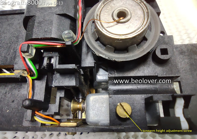
Another reason to make these arm adjustments now is if the tonearm requires any height adjusting to align with the fixed arm.

The adjustment screw for the tonearm height is inconveniently located on the underside of the tangential arm assembly which makes it a real pain to adjust later...it means removing the arm assembly again for the adjustment.  So now is the time to do it.


There is one other important tonearm related task while the arm assembly is open.

A common complaint of Beogram 8000 owners is that the Beogram starts dropping the arm onto a record instead of gently lowering it. Most of the time this is because the tonearm height adjustment screw touches the metal base of the tonearm (where the counter-weight is).  For some reason the arm lowering mechanism slowly lowers (via the solenoid) but the arm itself delays and does not follow it.
Then, suddenly, the arm drops down as the screw releases from contact with the base of the tonearm.
It is not magnetic as the adjustment screw is brass.  Nevertheless, I have witnessed this happening.
My solution is similar to what B&O does on the Beogram 400x tonearm lowering mechanism.  I place a thin piece of plastic material (Dura-Lar) between the height adjustment screw and the base of the tonearm.


This modification has always worked for me.

Moving on...Here are the tangential arm assembly main parts removed and cleaned.


For mounting the spindle back onto the floating chassis, I use some red grease for the two mounting ends.

For the two rails, I use some dry lubricant for the shiny, smooth rail surface.

For the spindle itself, I have plenty of the original lubricant mixture called out in the B&O service manual.  That is Rocol MTS grease mixed with Esso NUTO oil.
I have mentioned this before, I use this mixture because I happen to have it. If I didn't have it, there are modern, synthetic oil substitutes that can be used.  Just remember to not over do it when oiling the spindle.
The spindle spins so too much oil will result in oil being distributed all over the inside of the Beogram as the spindle turns.

Here is a photo of a test fitting of the cleaned tangential arm components prior to lubrication.


Reassembling the tangential arm spindle, spindle nut, bracket and rear rail can also test your patience a bit.  I like to test fit it before doing it with oil applied.


Here is the tangential arm assembly reinstalled on the floating chassis.


I combined all of the components for this Beogram 8000 for a quick test of some basic functions (Play start, platter scanning, speed adjusting, return to Stop).

Everything I wanted to check worked.


Very nice to see.  A major milestone in this restoration.

For the next post I will make the necessary service manual adjustments to prepare for record play and perform the first test play of a record.