Featured Post

Beogram Commander Remote Control: Maybe This is the Final Version!..;-)

This is a follow up to my recent post about the redesigned Beogram Commander remote control board, which now works in both (DC-motor) Beogr...

Sunday, May 31, 2020

Beogram 4000: A New Arrival From Michigan - A First Look

Another Beogram 4000 recently arrived from Michigan for a restoration. I had sent out a double box shipping container with detailed instructions, and so shipping went well. This shows the unit as received:
The aluminum surfaces are in pretty good shape, but there is one ding on the plate that surrounds the platter:
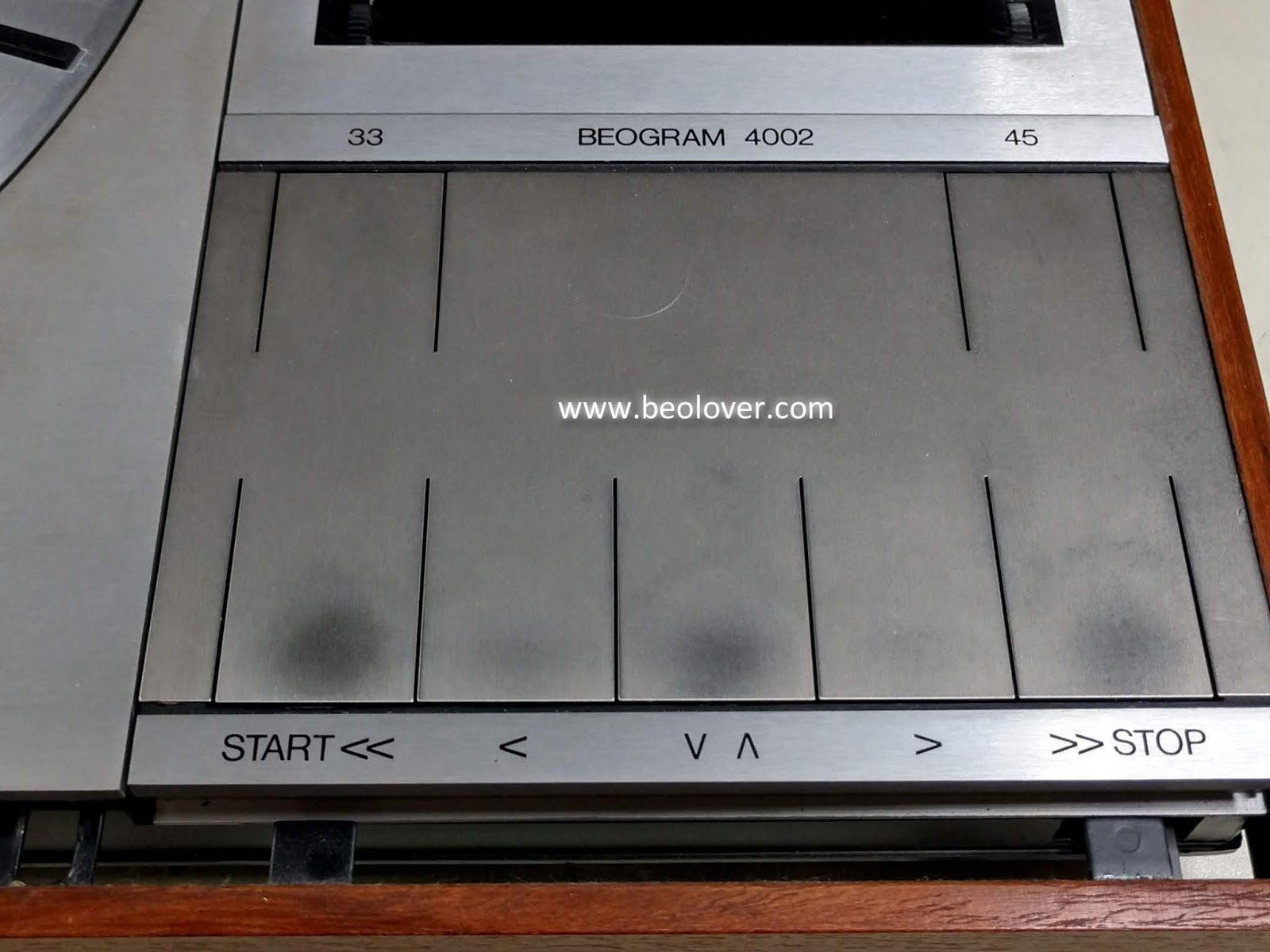
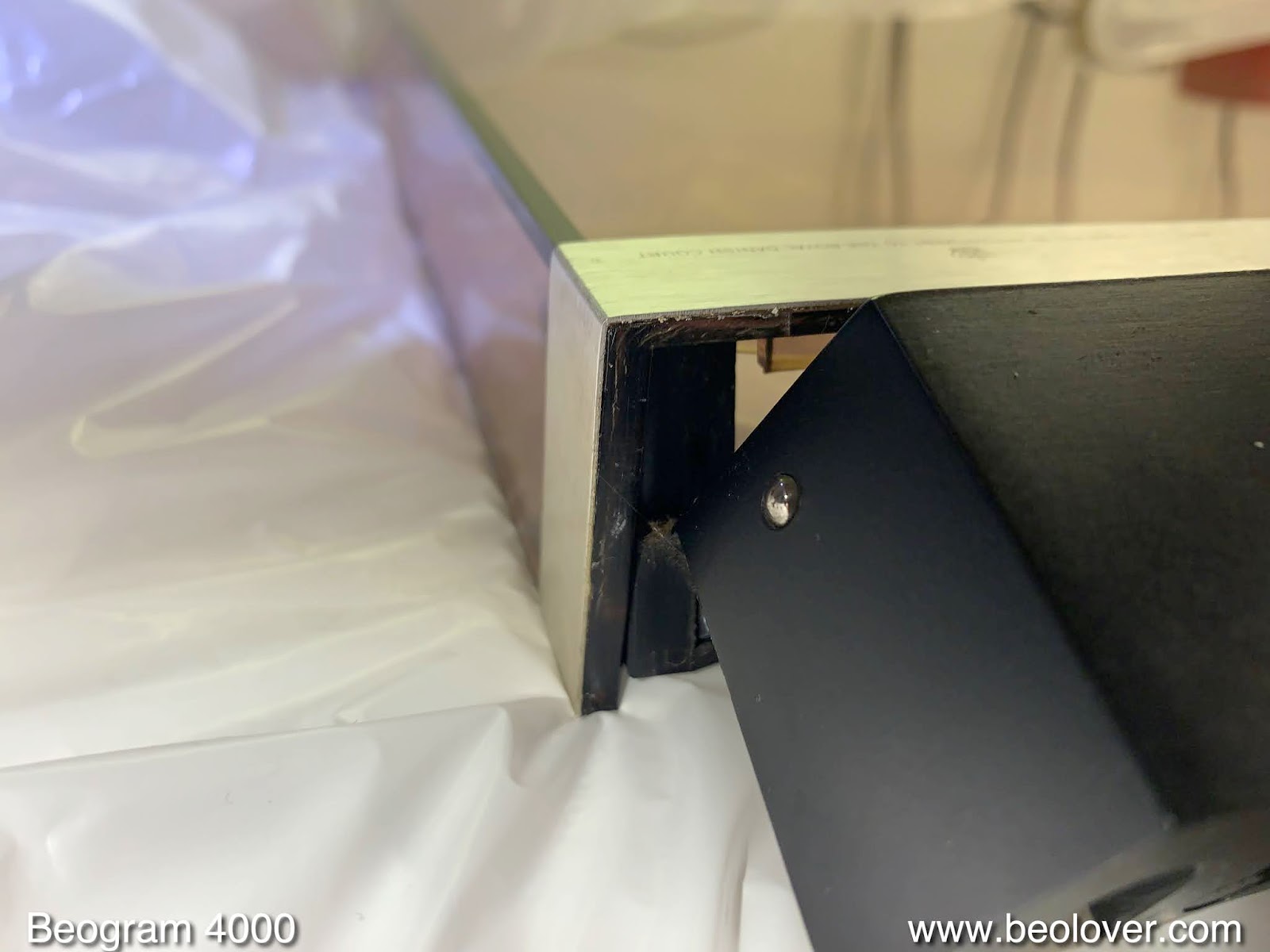
The platter itself is in pretty decent condition, and so are the keypads and small aluminum plate. Unfortunately the plinth had one corner 'shaved' at some point:
Luckily, the owner sent a set of plinth panels along, which I will transfer to the metal frame that holds them in place around the enclosure. The hood is badly scratched, but is seems mostly on the outside, so I should be able to polish it back to a decent state.
The black hood hinge and the back end of the enclosure show the often found corrosion marks:
I may need to sand and paint, or use spare parts from another Beogram.

Under the hood the unit seems in original condition, which is always the best starting point for a restoration. The contact terminals of the mechanical switches show the usual strong oxidation and signs of attempts to make them function better by bending them out of shape:
This means one has to extract them and straighten them out. I usually plate them with nickel and gold during this process to prevent future oxidation.
This is an early 4000, as indicated by the motor pulley without side walls, and the external belt guides:
I later models this setup was replaced by a pulley that has sidewalls to prevent the belt from falling off, which allowed eliminating the separate guides.
During shipping the cracked plastic pulley came off:
But due to placing cut to size foam under the hood the carriage did not 'go rogue' and so damage was prevented. The unique red position indicator usually breaks when the carriage liberates itself from the pulley, but in this case it survived:
On the sad side, some tape was placed directly on the arms cover, which lifted off some of the lettering:
Unfortunately, the ubiquitous later 4002 and 4004 versions state "Tracking Force Adjusting" instead of "Tracking Weight Adjusting", i.e. it is difficult to find a replacement with the correct lettering.
After this visual inspection, I reinstalled the pulley and pressed ON and the unit came to life. A good sign is that the strobe bulb works fine.
The carriage also started moving sluggishly, and the LP set down point was found and the arm tried to lower itself, but the mechanism is stuck due to hardened lubricants. Nothing unexpected.

Bottom line: This unit is a decent starting point for a full restoration, and I am pretty confident that it will come out with a like-new performance, but a few small cosmetic flaws. But most have some 'wrinkles' after ~50 years of service life (like the Beolover...;-).


Beogram 4002 Type 5513: Recapping the main controller board and the output board

The capacitor replacement on the main controller board and the output board are complete.

Along with replacing the electrolytic and tantalum capacitors on the main board I also replaced the RPM selection relay plus the two RPM adjustment trimmers.


This photo shows two components on the main controller board that I will possibly have to return to and modify. They are for the record detection circuit. Once I am at the point of measuring all of the Beogram 4002 photo sensors I will see if these two components will need changing.


On the output board is another relay to be replaced. It is for the phono muting. Along with the relay there is one electrolytic capacitor that was replaced and I added a grounding switch to provide the option to connect or disconnect the Beogram 4002 signal ground with system ground. That option allows the owner to deal with any hum issues.


Here are the two boards recapped...

Main Controller Board before


Main Controller Board after


Output Board before


Output Board after


Here is a photo of both boards completed


Now on to the tangential arm assembly components.

Tuesday, May 26, 2020

Beogram 4002 Type 5513: Beogram 4002 Bonanza!

It seems like we are up to our ears with Beogram 400x turntable restorations.

Beolover is busy with a few projects and I have two Beogram 4002 Type 5513 projects that I started looking at back in February of 2020. In those posts I sent four Beogram 400x platter motors to Beolover to do his restoration magic on. He finished those motors and they are back in my hands, ready to use.

After getting bogged down with a lengthy Beomaster 4400 restoration I am ready to get back to work on these two Beogram 4002 Type 5513 turntables.

Lets start with the local Beogram 4002 an owner dropped off.
Here is a quick recap of its condition.


A very nice Beogram 4002 turntable. It has some wear on the push buttons as most of these turntables have at this point in their life.


I has a nice MMC-20CL phono cartridge. A consensus favorite among Beogram 400x and 8000 owners.


Inside you can see in the lower left of the Beogram case that the platter motor has already been removed.  It has been refurbished by Beolover and will soon go back into this Beogram.


The plastic spring clips for mounting the Beogram platter speed indicator are in perfect shape. So often they are cracked.


The sticker on the transformer verifies this is a Type 5513 Beogram 4002 and shows the serial number.


The tangential arm transport pulley is starting to show some age cracks.  I will replace the plastic pulley with an aluminum one.


Now to remove the two circuit boards for my restoration part. That will be to replace the aging capacitors, calibrate the platter speed, install new speed control trimmers and various other tasks I will be showing on this thread.


I will start on the two circuit boards tomorrow.

Monday, May 25, 2020

Beogram 4002 DC Motor Restoration

A Beogram 4002 DC motor arrived from Norway for restoration. This shows the motor as received:
I did the usual initial bench test by applying ~4V between the blue and the red leads. This motor did not turn at all, but the bench supply showed a short circuit. Not a great sign. I removed the outer enclosure and found that the tabs that hold the upper bearing in place were bent up. A sign of previous human interaction with this motor:
I opened it up and this impression was fortified by the bent commutator brushes:
I extracted the bearings (the two small donuts on the black pad):
and immersed them in motor oil and pulled a vacuum:
Immediately, vigorous bubbling started, indicating that the vacuum pulled air from the empty pores of the Oilite bearing material. This process makes room for fresh oil to diffuse into the bearing, refreshing its ability to lubricate the shaft.
After ~72 hrs the bubbling stopped and I extracted the bearings and re-assembled the motor. I tried to run it again from the bench supply, but it still showed a short circuit.

This indicated that at least one of the three motor coils was short circuited by its spark snubber. I took the rotor back out

to replace the snubbers. They are the three devices (one has a red dot) connected with wires between the rotor poles.
I removed the snubbers. This shows them next to the modern TVS replacements:
I soldered the TVS device into place:
If you try this at home, make sure you press the TVS units into the rotor windings until they are above the commutator. Otherwise they will interfere with the brushes potentially stopping the motor rotation.
I put the motor back together and now it ran nicely from the bench supply. Time to do a 24 hrs RPM stability test with the BeoloverRPM device in one of my Beogram 4002s:
The BeoloverRPM allows logging the RPM in 10sec intervals for extended periods of time. Perfect for catching that intermittent RPM variation that otherwise might go unnoticed. This is the curve I measured:

This is pretty much as good as it gets with the Beogram DC motors. This motor is back in business!


Beogram 4000: Hood Restoration - Polishing and Exchange of the Hinge

The Beogram 4000 that I completed recently still needed its hood restored. Of the two hoods I received, one had a crack up front at the left corner, while the other had a decent plexiglass body, but the hinge showed corrosion blooming under the black paint:
This is a frequent issue with Beogram 4000 hinges, and one can fix it by sanding the hinge down and then repainting it with black matte spray paint. But the better solution is to find a hinge that does not have this issue, since spray paint is never perfect. Luckily, the cracked hood had a near perfect hinge, and so I decided to exchange them.
Taking the hinge out is not difficult, but one has to get under the easily damaged aluminum  strip that graces the hoods in the back. This can be done by carefully inserting a razor blade between the plexiglass and the strip:
One needs to be careful to not damage the plexiglass around the strip or the strip itself. They easily break off at the bend. So it is best to not bend them out too much. This is enough:
It is important that it also comes off a bit at the bottom, which usually happens due to the age of the glue - if it does not: It may be best to heat the hood to ~70C in the oven and then carefully pushing the strip down at the bottom. The heat softens the glue making it come off much more easily. But let it get too hot, and the plexiglass starts deforming, so it is a bit of a scary thing to do. Luckily in this case the strip came off fairly easily without too much convincing necessary, so I did not have to go to the oven treatment. Once the strip is off, just remove the two screws on both sides and the hinge comes off. The replacement is easily bolted in and then the remaining task is to glue the aluminum strip back on. 
In the past I used double sided tape, but I had to realize that in some cases the strips lifted off again after a few months. Pretty un-beolovely! Therefore, this time I decided to try out contact cement, which, I think they also used initially when they made these hoods.
The first step is to remove the old glue, which can be softened by placing paper towel wads drenched with isopropyl alcohol into the gap and let it sit for ~30 min:
After this treatment, the glue can be scraped off with a razor blade:
Now it was time to apply a thin layer of contact cement to both sides with a tooth pick. I use this (Amazon):
It is important to not apply too much cement, and also stay ~1mm away from the front edge of the strip, since some glue can be squeezed out there when the parts are pressed together. 
After the cement is fully dry (~15 min) the strip can be pressed into place. Since the strength of contact cement bonds strongly depends on the force and duration applied when pressing the parts together, I developed a set of clamps specially designed for the task (it is difficult to just use carpenter clamps or similar due to the irregular shape of the hinge mechanism):
I pressed the strips back into place by hand and then applied the clamps:
I let everything sit for a day, and then removed the clamps:
Nice how precisely the strip conforms around the corners! Beolovely!
After this it was time to polish the hood, since it was pretty scratched on top:
I started out with sanding it with a 320 grit until all the scratches were gone, and then I polished it back up to translucency in 10 steps with ever finer grit and finally with polishing compounds. A nice 2 hrs workout in the garage, and then the hood looked pretty nice again:
The final touch was to install new rubber bumpers for that satisfying 'plonk' when closing the hood. The original ones are usually gone at this point in time since the rubber degrades over time:
The sticky remnants of the old rubber can be drilled out with a 2 mm drill bit:
(be careful when you try this at home - it is easy to break out the plexiglass corner if one is not careful during this procedure). Once the old stuff is gone, a new piece of 2 mm O-ring can be glued into place with super glue gel. Once the glue is hardened, cut the O-ring snippet to 1mm length above the plexiglass:
Allright! Another Beogram 4000 re-hooded! Soon I will send this beauty back to its owner!