Featured Post

Beolover SyncDrive: DC Platter Motor Replacement for Beogram 4002 and 4004 (Type 551x and 552x)

Late Beogram 4002 and the 4004 (Types 551x and 552x), which have DC platter motors instead of the earlier synchronous AC motors usually suff...

Showing posts with label RPM trimmers. Show all posts

Saturday, July 3, 2021

Beogram 4004 for the Workshop: PCB 1 & PCB 8

In this post I performed the restoration work on the main board (PCB 1) and the output board (PCB 8).

However, I started off the capacitor replacement in the cabinet with the power supply 4000uF filter capacitor.  I replaced the old electrolytic capacitor with a new Nichicon electrolytic capacitor in Beolover's 3D printed housing. The power supply filter capacitor style changed on various types of Beogram 400x turntables. This Type 5526 Beogram 4004 uses a single filter capacitor.


Next I started in on removing the main board and the output board for their restorations.
While doing that I did some more assessment on other components inside this Beogram.
The button control panel works fine but I can see that the switch contacts will likely need some cleaning. 

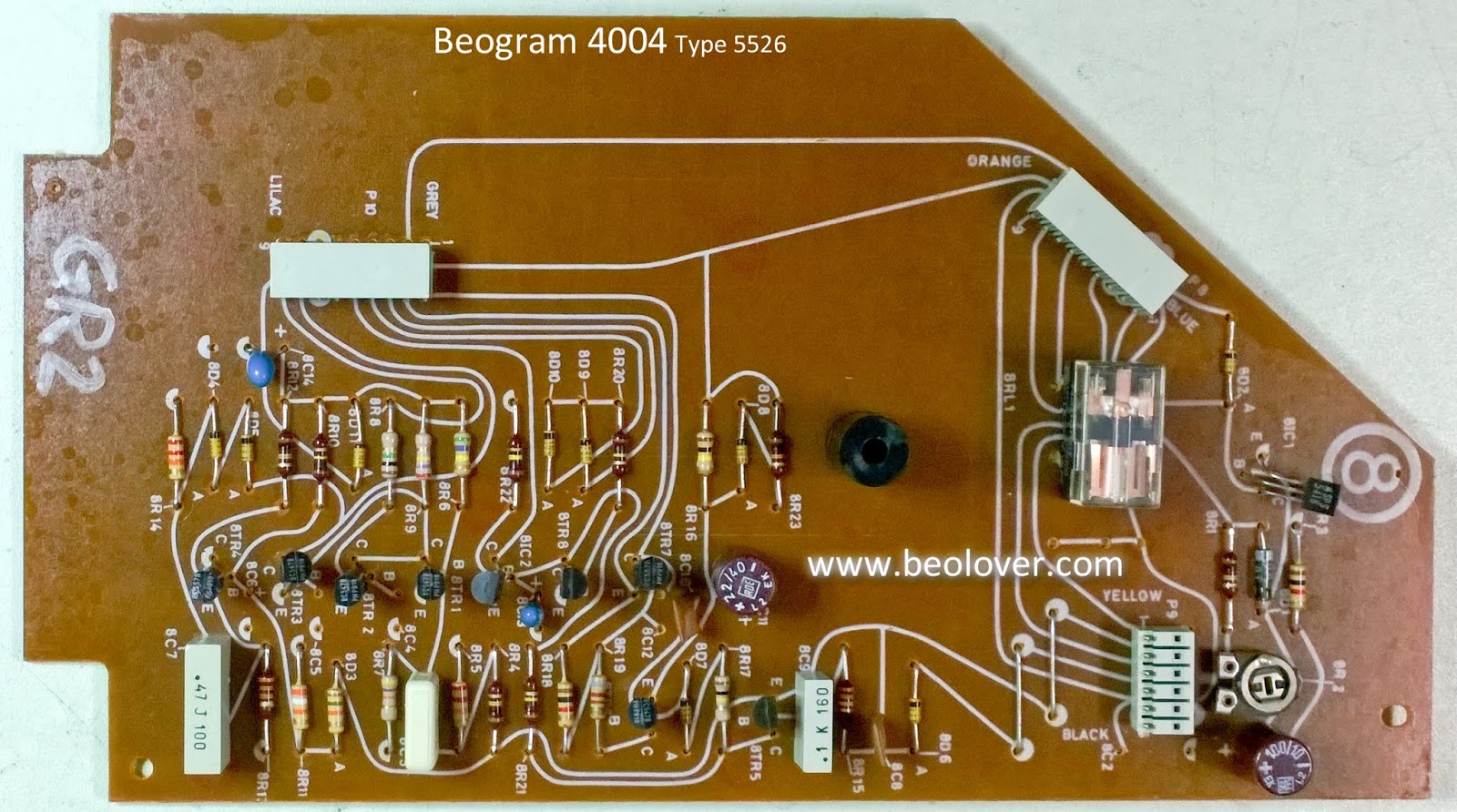
It is necessary to remove the button panel and disconnect three cable connections to get to the output board (PCB 8).

PCB 8 contains the audio (from the phono cartridge) signals to the phono cable going to a preamplifier.
There is an audio muting circuit there that switches the audio signals (Left & Right) to ground when the phono signal is muted.

PCB 8 also contains an early remote control system between a Beomaster 2400 and a Beogram turntable.  The Beomaster 2400 contains the actual remote control.  It uses an additional two pins in the phono cable DIN connector (pins 6 & 7) for the wired remote control integration with the Beogram 4004.


PCB 1 is the main board and contains all of the Beogram analog control circuits.


I removed the boards from the cabinet to do the restoration work on them.
I usually begin with the PCB 8 output board because it is smaller and easy to do first.

Again, the audio output/muting circuit is highlighted along with the remote control circuit.
One thing a little interesting on the audio output circuit is the signal ground and system ground connections on the output cable connector.  Some Beogram 4002/4004 turntable PCB 8 boards have a small capacitor (8C2, 47nF) between those pins.  This Beogram 4004 has that capacitor removed.  I have seen this on several Beogram 4004 units and I am not sure whether there was some B&O service bulletin about it or not.


Since this PCB 8 board had 8C2 removed I decided to use those PCB holes to mount a small toggle switch that will connect/disconnect signal ground withe system ground.  This can be used to make that selection choice when addressing any hum in the phono signal between the Beogram 4004 and an amplifier.

Here is the reworked board.
I replaced all of the electrolytic and tantalum capacitors 4.7uF and smaller with WIMA MKS non-polarized capacitors.  I also replaced the original, National muting relay with the Beolover Omron replacement.


That takes care of the output board.
Now on to the main board.


I used the same strategy on the capacitor replacement but I should note the in many cases, including this one, I have found that the existing tantalum capacitors are often still good. I still like replacing them with WIMA non-polarized capacitors as that should mean one less thing to worry about in the future. Preventative maintenance I believe it is called :-).
Many times however, we get Beogram control boards from units that were not stored in good environments so we definitely want to change the tantalums and electrolytic capacitors in that case.

I will change out two trimmer resistors on this board.  1R15 (33 1/3 RPM adjustment trimmer) and 1R14 (45 RPM adjustment trimmer).  The speed selection relay will also be changed from the original National relay to the Beolover Omron replacement.  Beolover has demonstrated many times that these replacements are effective in platter speed consistency along with the platter motor restoration.


Another main board change is resistor 1R26 and transistor 1TR3.
Those are key in the Beogram 4002/4004 fixed arm sensor's record detection circuit.
For long term reliability and stability we check the transistor gain to see that it is at least 500.
If not we change the transistor to a new one that is.  The 1MΩ 1R26 resistor is changed to a 5MΩ trimmer resistor. Together with the 500 Hfe 1TR3 transistor it will be easy to set the steady state voltage level of 1TR3 so the Beogram 4004 record detection circuit operates at its optimum capability.


In this case the original 1TR3 has a gain of under 500 so I went ahead and changed it.  The Beogram record detection still worked without this change but I make the change because it will be more reliable in the future. 


The replacement transistor has the collector and emitter leads reversed with respect to the transistor case shape.  It is always a good idea to test and check that the orientation of a new transistor matches the original one.


Here is what the new 1R26 and 1TR3 will look like installed in the PCB 1 board.


I soldered the 1TR3 transistor but I will temporarily mount the 1R26 trimmer on the trace side of PCB 1 so I can easily make the setting of the resistance value.  Once I have that dialed in I will remount the trimmer as shown above.

Here is the reworked PCB 1 board.


Here is the trace side with the 1R26 trimmer temporarily installed for adjustment.
I also placed two PCB 1 capacitors on the trace side so they can't interfere with the floating chassis movement.  They sit right above the floating chassis so these WIMA replacements are better on the PCB 1 trace side where they will be out of the way.


That does it for the PCB 1 and PCB 8 restoration work.
The next step will be to reinstall the boards and do some initial voltage checks.

Monday, June 15, 2020

Beogram 4002 Type 5513: Third Beogram From Houston Restoration Continues

The Beogram 400x Bonanza continues as I completed one Type 5513 turntable and move on to the next one. This one continues a owner in Houston's third Beogram 4002 Type 5513 turntable restoration.

As I showed in the initial assessment back in March, this turntable is in nice shape and a great candidate for restoration.

Like the previous Beogram 4002 Type 5513, I already had Beolover restore the platter motor of this turntable and have it ready to be put back into service.

I decided to start the rest of the restoration on this Houston Beogram 4002 with the electrical work...recapping the usual two boards, changing the two relays, replacing the platter speed trimmers and preparing the added trimmer for the eventual record detector circuit checks.

Here is the main board before the restoration steps.


I went ahead and prepared the trimmer replacement for 1R26 and checked the current gain of the 1TR3 transistor (the two components that we look at for the record detection circuit).


The transistor measures great.  I removed the original, fixed resistor 1R26 and fit the replacement trimmer.


That is where the trimmer will eventually go.  For now I will temporarily fit it on the trace side of the board where I can make the initial adjustments later.


I took a look at the 1C10 resistor that affects the platter motor stability.  The previous Beogram 4002 Type 5513 turntable restoration had a 33uF capacitor for 1C10.  This turntable has a 0.47uF capacitor.
I won't change the value on this one but it is interesting to note the difference.


Finally, here is the platter speed selection relay and the two speed trimmers of the original board. All three will be replaced.


Here they are replaced with a Beolover replacement relay and two muli-turn trimmers.


...and here is the main board after the electrolytic and tantalum capacitors have been replaced.


The next board is the output board. This is the board where the phono cartridge audio signal exits the Beogram.  The board has input and output connectors and a small circuit for muting the audio signal when the tonearm is not playing a record. The Beogram control system manages the muting relay on this board to occur when the tonearm is lowered and raised. There is a delay circuit on the board to adjust when the relay turns on the audio signal after the tonearm sets down on a record.

I always replace the original muting relay with a new Beolover replacement relay. The electrolytic capacitor for the delay circuit is replaced as well.  I also add a small switch that can connect/disconnect signal ground from system ground. That option allows for Beogram 4002 phono connections to non-B&O preamplifiers to compensate for any grounding differences that can cause hum in the signal.

Here are the before and after photos of the output board restoration.

Before


After


While I had the soldering iron hot I went ahead and replaced the two RPM speed indicator lamps with Beolover LED modules. As mentioned in previous Beogram 400x restorations these two lamps are part of the platter motor circuit and the Beolover LED modules provide some added stability.


There are a couple of electrical tasks in the Beogram 4002 cabinet and the tangential arm assembly (like the reservoir capacitor and the arm position sensor lamp) but I will dive into some of the mechanics of the Beogram 4002 next.


Sunday, May 31, 2020

Beogram 4002 Type 5513: Recapping the main controller board and the output board

The capacitor replacement on the main controller board and the output board are complete.

Along with replacing the electrolytic and tantalum capacitors on the main board I also replaced the RPM selection relay plus the two RPM adjustment trimmers.


This photo shows two components on the main controller board that I will possibly have to return to and modify. They are for the record detection circuit. Once I am at the point of measuring all of the Beogram 4002 photo sensors I will see if these two components will need changing.


On the output board is another relay to be replaced. It is for the phono muting. Along with the relay there is one electrolytic capacitor that was replaced and I added a grounding switch to provide the option to connect or disconnect the Beogram 4002 signal ground with system ground. That option allows the owner to deal with any hum issues.


Here are the two boards recapped...

Main Controller Board before


Main Controller Board after


Output Board before


Output Board after


Here is a photo of both boards completed


Now on to the tangential arm assembly components.

Thursday, December 27, 2018

Beogram 4004 Type 5526: Recapping the boards on the second Beogram 4004 from Texas

I removed all of the components that were necessary from the Beogram cabinet to clean out all of the debris from the old transport bushings.


The cabinet is now ready as I work on the individual components.

I decided to tackle the recapping of the two circuit boards first.
Here is the main (controller) board before the recapping. Note that the RPM relay on this Beogram controller board is the National type of relay. It has a different footprint than the Siemens relay used on the first Beogram 4004 I restored. Beolover's replacement relay assembly comes in both sizes so that isn't a problem. You do need to check that before ordering a replacement relay for your project.


Here is the output board. It also has the National type relay. So far I have found that whichever type of relay (Siemens or National) is used it will be on both boards.


On the recapping of the controller board I replaced all of the electrolytic capacitors and tantalum capacitors with 105°C, Japanese electrolytic capacitors or WIMA MKS capacitors. The two trimmers for the 33⅓ RPM and 45 RPM platter speed calibration were changed to sealed, multiturn type trimmers. I also changed capacitor 1C10 from the original 0.33uF to 10uF. The reason for that is because the stability testing on the DC platter motor after Beolover's restoration process showed that the 10uF value provides more stable speed results.

Here is the recapped controller board.


On the output board I also replaced the electrolytic and tantalum capacitors with 105°C Japanese electrolytic capacitors and WIMA MKS capacitors. The muting relay was traded out for the Beolover replacement relay and our usual grounding switch was installed. The grounding switch provides more options for the phono cable connection to non-B&O preamplifiers. In most cases it eliminates the need for the extra, external grounding wire from the Beogram to the preamplifier.


Both boards are ready to use.

Tuesday, December 11, 2018

Beogram 4004 Type 5526: Recapping the boards

There are just two boards to replace capacitors on in the Beogram 4004. In addition to the capacitors there are two relays that can eventually fail so I always replace those with a modern sealed relay assembly supplied by Beolover. The relay on the main board is for platter speed selection (33⅓ RPM & 45 RPM).  The relay on the output board is for the phono cartridge muting. There are two trimmer resistors on the main board that I also replace. Those are the platter speed adjustment trimmers. The replacement trimmers are sealed, multi-turn type trimmer resistors.

Here is the before picture of the main board.


Here is the main board after the updates. The 1C10 capacitor was changed from its original 0.33uF value to 10uF. The reason for that is due to the rebuild testing of the DC platter motor. When Beolover rebuilds the motors he tests them for stability using the different 1C10 capacitor values that Bang & Olufsen used in these turntable controllers. On the tests for this rebuilt motor Beolover found the 10uF value to be the best pairing.


Now for the output board. Here is the before shot.


...and the after shot. Note that I added a small switch to the output connector to allow shorting signal  ground to system ground. That shouldn't be necessary when connecting the Beogram 4004 to a Bang & Olufsen amplifier via the DIN plug. However, when connecting to a non-B&O preamplifier there can sometimes be a hum in the signal. The Bang & Olufsen provided adapter cables for DIN to RCA plug type hookups included an external grounding wire for this purpose. The switch makes it convenient to just set the grounding as necessary inside without an extra wire.


There is one reservoir capacitor in the Beogram 4004 cabinet that needs replacing. I replace that capacitor with another Beolover custom part. The Beolover part is designed to mount perfectly in the original clamp.


Here is the new reservoir capacitor installed. It fits perfect and looks great.