Featured Post

Beolover SyncDrive: DC Platter Motor Replacement for Beogram 4002 and 4004 (Type 551x and 552x)

Late Beogram 4002 and the 4004 (Types 551x and 552x), which have DC platter motors instead of the earlier synchronous AC motors usually suff...

Showing posts with label Beogram 4004 Type 5526. Show all posts

Saturday, July 9, 2022

Beogram 4004 Type 5526: Ready for record play

In this post I wrap up the service manual adjustments and reassemble the Beogram 4004 so I can begin playing records.

The first service manual adjustment is to set the platter height so the surface of the platter is 23mm from the top of the fixed arm.

I set my calipers to 23mm then adjusted the platter bearing screw so the platter measured 23mm from the top of the fixed arm.


Next, I adjusted the tonearm lowered position limit so the tip of the stylus is about 1mm from the top of the first platter rib.


Then I checked the stylus tracking path by stretching a string from the center of the platter to the edge of the Beogram cabinet.  As I placed the stylus at various points along the string I checked that the distance of the stylus to the string stayed consistent.


Following that adjustment procedure I checked the tracking sensor sensitivity.


With a test record on the platter, I lowered the Beogram 4004 tonearm onto one of the middle tracks.
The platter was not connected to the motor (the belt was removed) so nothing was moving.  
I manually rotated the platter and observed when the servo begins to move the spindle (to track the record)
.
The Beogram 4004 servo should start rotating the spindle pulley within one or two platter revolutions after the tonearm sets down.  After that the servo should move the spindle on every revolution.
I set the tracking sensitivity to rotate the spindle after one revolution.

All of the adjustments so far were without the platter belt installed.  Any moving of the platter was done manually.

Now it was time to install the platter belt and begin checking the platter speeds (33.3 and 45 RPM).
For the platter speed adjustment I used the two trimmers that were installed on the reworked PCB 1 board to adjust the 33.3 and 45 RPM turntable speeds. The speed adjustment knobs on the speed indicator panel were set to the 0 position.

I use the Beolover RPM Tool to check the platter speed as I adjust the speed trimmers. The following two pictures show the RPM tool and adjustment.


The last adjustments are to put the Beogram 4004 deck panels back together and check that everything aligns.  

The platter needs to be centered in the deck opening and the top of the platter should be even with the top of the deck plate.

Those adjustments can take quite a while to get correct and you often have to go through several iterations of the adjustments.  That was the case here although it wasn't really to bad.

Here are the pictures of the Beogram after all of the adjustments were complete.


This Beogram 4004 is ready for playing records.
I will test this turntable in a listening room for a few days to make sure everything works properly before returning the Beogram to its owner.

Friday, July 1, 2022

Beogram 4004 Type 5526: Control Signal and Sensor Signal Measurements

In this post I will show some bench measurements of this Beogram 4004.
It has been performing great and it is time to look at what is going on electronically (since I completed all of the electrical work).

I used an oscilloscope to monitor four key control signals.  Then I measured the Run-Off Stop circuit signal from the position sensor.  Last, I measured what the record detection sensor circuit looks like as measured at transistor 1TR3.  

Here is the relative part of the schematic that shows the four control test points I measured.
I wanted to capture those test points for various key Beogram control events (i.e. Start, Stop, Cueing, etc.).


Highlighted on the diagram are four control signal test points (ON, OFF, Cue Down and Cue Up).

Note: B&O changed the wording on the Beogram 4002/4004 control buttons so in some Types there are buttons: ON (<<) and OFF (>>) while on other Types the buttons say START (<<) and STOP (>>).

The diagram also shows 1D41 where I measured the Run-Off Stop signal.

Here are the test point wires connected for making the measurements.  It also shows the test point wires for the Record Detection circuit and the Run-Off Stop.


The following three pictures are oscilloscope screenshots for various Beogram 4004 events.

Viewing Tip: If the enlarged photo is too small to read the printed measurements, right-click the photo and select "Open link in new tab" or "Open link in new window".  The image in a stand-alone tab will allow you to zoom in for more detail.

In the first grouping I have a reference measurement of the four test points when the Beogram is turned off.  Next to it are the signal measurements when the START button is pressed.
Below those two measurements are the signals when the Beogram finds the set down point and lowers to play a record.  Last, are the signals when the arm is lowered and playing a record.


The next grouping continues with another picture of the control signals during record play.
That is followed by a cue up (arm raised), pause event.
The third picture shows the signals when the Beogram is operated in Slow Forward and Slow Reverse.
The final picture shows the signals when the Beogram is just paused over a record.

Note that the Cue Up signal is only active when the Beogram is in play mode and is either paused or scanning slowly (forward or reverse).  The Cue Up signal is off when the Beogram is scanning fast (forward or reverse) or cued down.


The final grouping shows the signals during the event where the Beogram is operated in Fast Forward mode until it reaches the ES (End Stop) switch and reverses to Fast Reverse.
The picture next to that is the event where the Beogram is in Fast Reverse mode and reaches the SO (Shut Off) switch.
The bottom left picture shows the event where the Beogram is cued down (playing a record) and the STOP button is pressed.  
The bottom right picture changes out the ON (<<) TP with the Run-Off Stop TP and shows the Run-Off Stop signal in relation to the OFF (>>) TP.


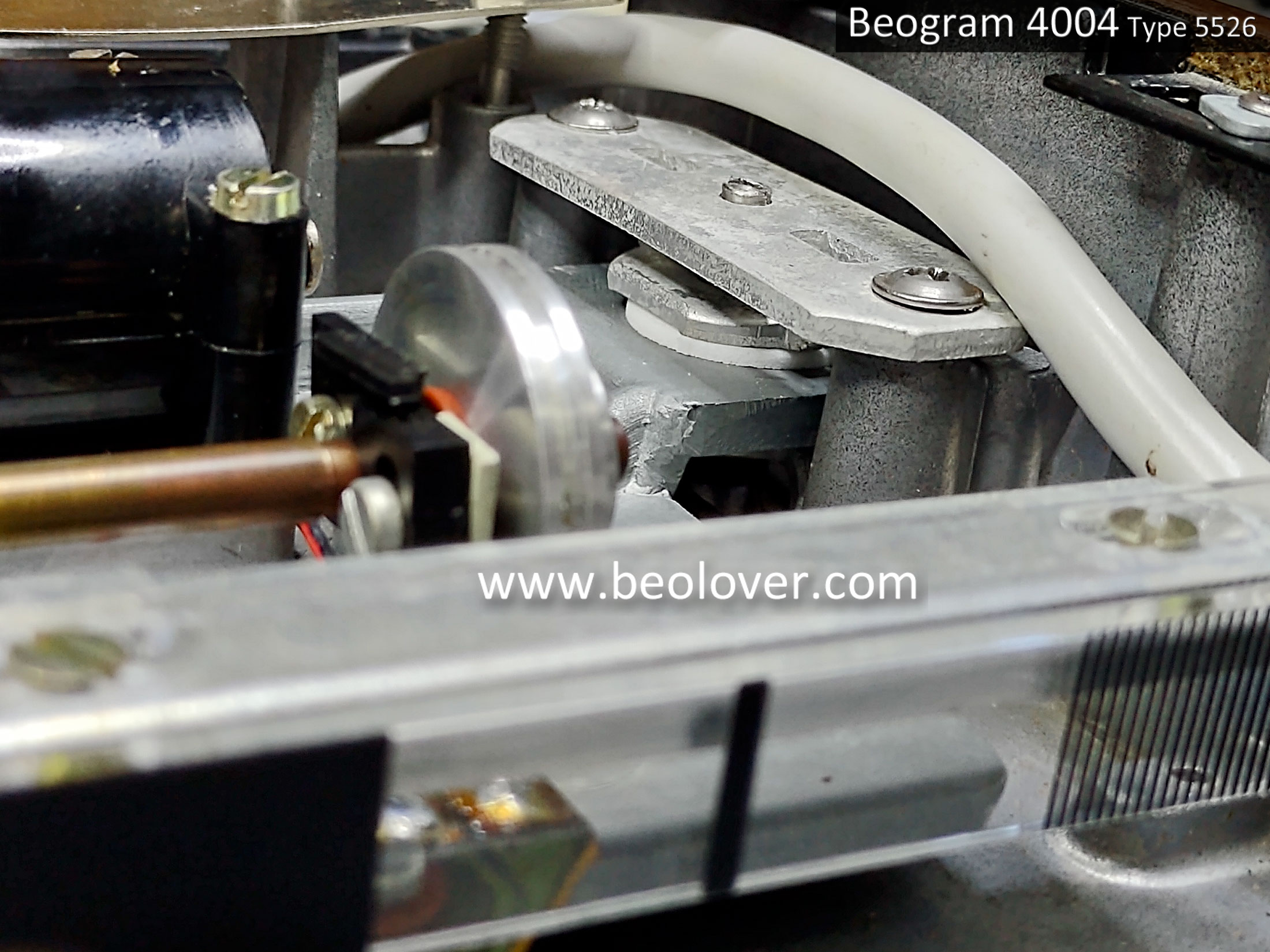
This photo shows the Beogram 4004 position sensor and scale that generate the Run-Off Stop signal.


This final photo of this post is another oscilloscope screenshot of the Record Detection circuit.
The test point is at the 1TR3 transistor collector and shows the signal generated by the Fixed Arm sensor over an empty platter (after processing through transistor 1TR3).


That is what I want to see.  A very healthy signal showing an empty platter.  The low part of the signal drops all the way down to zero volts and the peak is around six volts.  Very nice. 
This Beogram 4004 is performing great and in the next post I plan to wrap up the service manual adjustments.

Monday, June 27, 2022

Beogram 4004 Type 5526: Platter Motor, Detector Arm Adjustment and Solenoid Repair

Today I installed the Beogram 4004 platter motor, adjusted the position sensor collector voltage, adjusted the detector arm sensor and fixed a problem with the arm lowering solenoid.

From the checks I made in the previous post I knew there were adjustments that needed to be made on this project.  That is expected when new parts are installed.

I had also noticed that while the Beogram 4004 arm solenoid was engaging to cue the tonearm down, it was not cueing back up correctly.  There was a delay from when the raise tonearm signal occurs and when the solenoid disengages.  We have seen that problem before and it was with the solenoid plunger sticking.

First though...I wanted to adjust the steady state voltage of a couple of the Beogram 4004 sensors.
The adjustment trimmers are both on PCB 1.

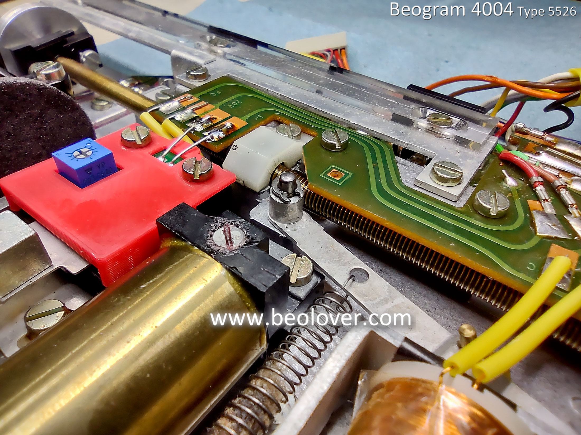
One is the position sensor (4IC1) steady state voltage level. I adjusted the 4IC1 collector to 5 VDC using PCB 1 trimmer 1R88.
Note: The 5 VDC voltage adjustment for the 4IC1 collector is made when the tangential arm is at a point in its travel where the position sensor lamp is shining through a clear section of the position scale.


After that adjustment I wanted to get the detector arm sensor adjusted using the new 1R26 trimmer...so I could move the trimmer to its final position on the component side of PCB 1.

I had to change my 1R26 trimmer during this adjustment because my initial 2MΩ trimmer did not have enough range.  The 1R26 trimmer shown below is a 5MΩ trimmer and it allowed me to set the voltage at the 1TR3 collector to 4 VDC (the desired steady state voltage level).


I de-soldered 1R26 from the component side of PCB 1 and moved it to the component side.


After the sensor adjustments I re-installed the Beogram 4004 DC platter motor.
This is the motor that Beolover restored back in January.

Here is a sequence of photos that show installing the platter motor, sub-platter, belt and top platter.


Things look great with the silent running platter motor that Beolover restored.

Normally I would move right into more service manual adjustments but I need to take care of the arm lowering, solenoid problem.

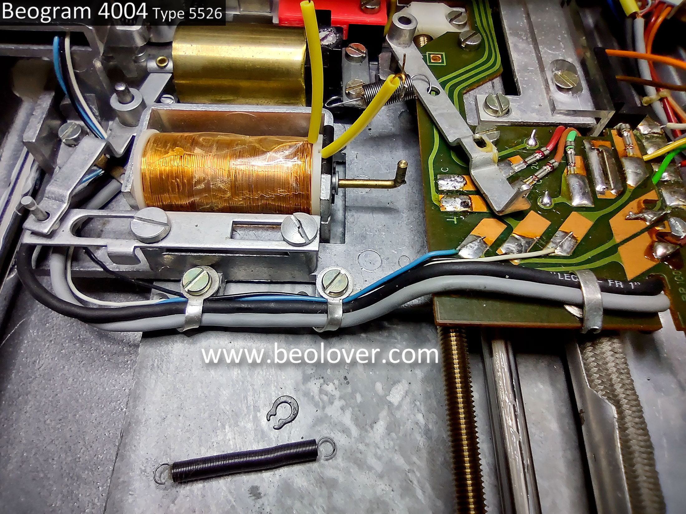
I removed the solenoid assembly so I could take it apart.


With the solenoid assembly removed I ran a check of the coil (it measured good... 9.3Ω) and energized the solenoid (using my 30V bench power supply).

When installed in the Beogram 4004 the Beogram controller applies a voltage of around 30 VDC to the solenoid to engage it.  The duration of that signal is less than 40 milliseconds then it drops down to around 1.8 VDC to hold the solenoid engaged.

When removed from the Beogram 4004 the solenoid engaged at a much less voltage (around 5 VDC and a current of 0.49 Amps).


The problem with this solenoid wasn't engaging though.
The problem was with disengaging.  The plunger was sticking.
When the arm lowering solenoid was disengaged I could feel resistance when manually trying to move the solenoid plunger to the raised tonearm position.

Here are the Beogram 4004 solenoid assembly components.


I cleaned all of the moving parts with acetone and I applied new tape to the coil as the original tape was coming off.

When a solenoid plunger is sticking it is tempting to apply lubricant to the moving parts.
Don't do that.  Oil and grease will make the problem worse and interfere with proper plunger movement inside the guide assembly.
The parts need to be smooth and clean which is why I used acetone to clean them (including the inside of the guide tube).

The solenoid sticking problem is similar to a Beogram 800x tonearm lowering mechanism sticking.
With a Beogram 800x there is a metal screw (used to adjust the parallelism between the tonearm and fixed arm) that sticks to a metal plate when in contact.  The solution there is to apply a thin layer of plastic between the two metal pieces so they don't make physical contact.

The same is true here.  The end of the plunger with the threaded hole for the control rod travels to the end of the guide assembly tube where it makes contact with the metal end stop.

After a period of time the two pieces of metal that make contact start sticking together.  Initially I thought it was a magnetic build up and I tried using a demagnetizer to solve the problem.  It appeared to do the trick but now I think it was due more to my cleaning of the solenoid components.

This time I cut and applied a thin piece of yellow tape (like that used to wrap the coils) to the end of the plunger. That prevents metal on metal contact when the plunger is all the way forward (arm lowered).


I could already see a huge improvement.
Prior to applying the tape I could manually move the plunger all the way forward but had resistance trying to move the plunger back.
Even when I turned the solenoid on end, the plunger would not fall out of the guide.
It just stuck to the end of the guide.
Now, since the metal ends are not making direct contact, the plunger easily slides back out.

Note: The thickness of the material is important.  In the past I tried using a thin, nylon washer on the plunger end as a barrier. The material wasn't thin enough and prevented the solenoid from lowering properly.

The proof is in actually testing the arm lowering and raising so I re-installed the solenoid and gave it a test.

It works perfectly now.  The arm raising is immediate.  No delay.


Note: In the above photos of the solenoid lowered/raised I hadn't re-installed the holding clip on the lowering lever pivot post.  That has been installed now.  In case anyone was worrying I missed that :-).

Now I can get back to the service manual adjustments.

Saturday, June 25, 2022

Beogram 4004 Type 5526: Reassembly for Adjustments and Testing

Today I started reassembling the restored Beogram 4004 parts back into the cabinet base.
My goal was to get the Beogram to a reassembled state where I could do some initial testing.
Things like applying power, checking some Beogram functions...basically an early validation that the restored components work.

Here are some photos of the Beogram 4004 cabinet base as I start adding the components.


Here are a couple of detailed photos of the new transport locks installed when the floating chassis was re-installed. The photo shows the Beolover transport lock bushings installed.


This photo is with the floating chassis locked down.


Here is the unlocked position.


Continuing on with the component reassembly...
Here is the floating chassis with the springs attached.


Here is the cabinet with the PCB 8 Output Board installed.


Next is with the PCB 1 main board, the keypad and the RPM display panel.


That is the minimum reassembly I wanted to do in order to run an initial power on test.
I did add one more item, a servo belt. 

The Beogram 4004 powered up and actually performed most of its basic functions.
The forward, reverse and up/down cueing all worked.  


That's a nice milestone to reach.
I can see a few things that will have to be adjusted but that is to be expected.
In the next post I dive into the service manual adjustments and check sensor signals.

Beogram 4004 Type 5526: Restoration work - Part 4

I wrapped up the floating chassis component tasks by reassembling the tangential arm assembly.
During the reassembly I performed some key lubrication tasks like new PMX - 200 silicone fluid in the lowering damper and a mixture of Rocol MTS 2000 grease with Mobile NUTO H32 oil.  
More modern lubricants are available today but I have plenty of the original lubricants called for in the Beogram 4004 service manual so I like to use those.

I applied some Molykote DX paste (grease) to the two tangential arm assembly rails first.


Then I opened the tonearm lowering damper to clean it and apply some PMX - 200 silicone fluid.


Next I mixed some Nuto H32 oil with Rocol MTS grease for the lubrication mixture on the tangential arm assembly spindle.


The Beogram 4004 tangential arm assembly components can now be reassembled on the floating chassis.


At this point I like to check the tonearm tracking force calibration.
The parts are easy to get to so it is a good place to calibrate the tracking force.


The Beogram 4004 floating chassis (and components) are ready to go into the base cabinet again.