My goal was to get the Beogram to a reassembled state where I could do some initial testing.
Things like applying power, checking some Beogram functions...basically an early validation that the restored components work.
Here are some photos of the Beogram 4004 cabinet base as I start adding the components.


Here are a couple of detailed photos of the new transport locks installed when the floating chassis was re-installed. The photo shows the Beolover transport lock bushings installed.

This photo is with the floating chassis locked down.
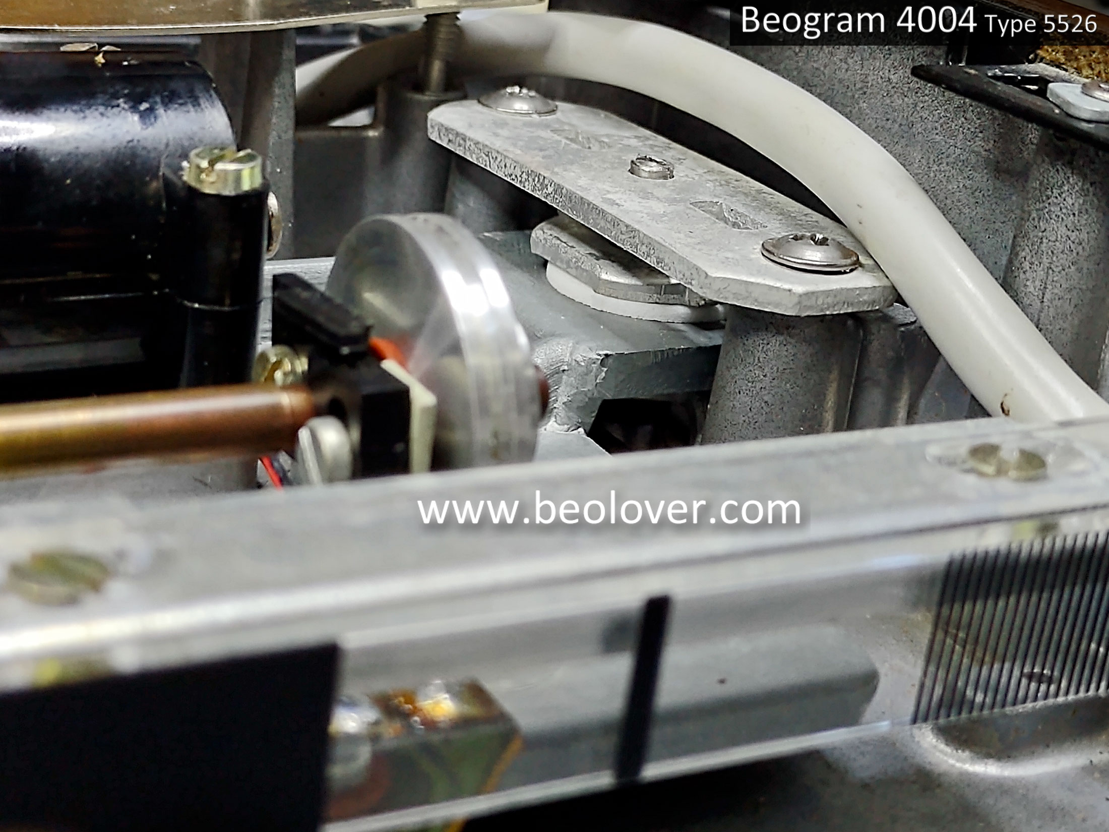
Here is the unlocked position.

Continuing on with the component reassembly...
Here is the floating chassis with the springs attached.

Here is the cabinet with the PCB 8 Output Board installed.

Next is with the PCB 1 main board, the keypad and the RPM display panel.

That is the minimum reassembly I wanted to do in order to run an initial power on test.
I did add one more item, a servo belt.
The Beogram 4004 powered up and actually performed most of its basic functions.
The forward, reverse and up/down cueing all worked.

That's a nice milestone to reach.
I can see a few things that will have to be adjusted but that is to be expected.
In the next post I dive into the service manual adjustments and check sensor signals.
No comments:
Post a Comment
Comments and suggestions are welcome!