Since the last post I have jumped into the Beogram 4004 restoration tasks.
I am going to show the before and after pictures of the PCB 1 and PCB 8 capacitor replacements but I am also going to show a few other tasks that I performed along the way.
Before tackling the PCB 1 and PCB 8 part replacements I wanted to get the problem of the End Switch (ES) and Switch On/Off (SO) switches resolved.
The previous post showed the broken ES switch. I decided to replace both the ES and SO switches with a good set from a spare Beogram 4002 Type 5513 unit.
Here are a couple of before photos -


Here are the two replacement switches installed -

While I had the Beogram 4004 floating chassis components in front of me I continued by disassembling components I am going to replace or restore.
Next, I removed the servo motor and the tangential drive spindle/pulley assembly.
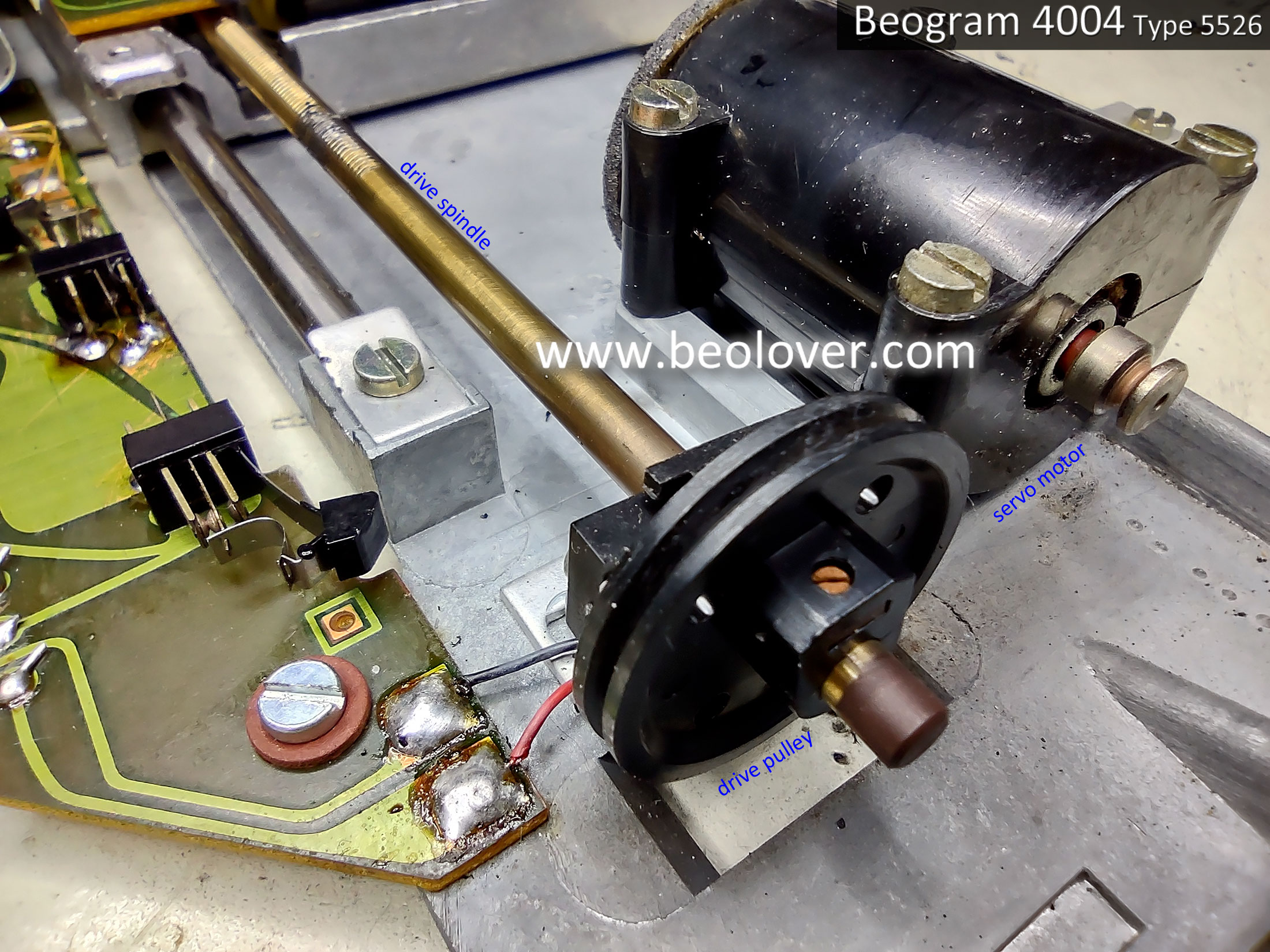
Here is the servo motor opened up.
The foam padding is still intact but pretty brittle. It will eventually completely dry out and start breaking into pieces so I will replace it with new vibration damping material.

I cleaned the spindle with a brush and some alcohol.
I removed the original, plastic pulley from the spindle and installed an aluminum pulley.


Next, I removed the original tracking sensor lamp assembly to prepare for the installation of the replacement Beolover Beogram 400x tracking sensor lamp assembly.
With the tangential drive spindle removed the tangential arm assembly can easily be slid up and down the two guide rails. This is a good time to clean them before applying new grease.

That is all I am going to do on the floating chassis components for now.
It is time to move on to the work on PCB 1 and PCB 8.
Once those are complete I will return to the floating chassis to install the new Beolover tracking sensor lamp assembly along with replacing the fixed arm, record detection lamp (also a Beolover lamp assembly).
Here is the before photo of the Beogram 4004 Type 5526 PCB 1, the main turntable electronic control circuits.

Here is the PCB 1 after photo...after the capacitor replacement has been done, a new platter speed selection relay has been installed, new trimmers for the platter speed control, new trimmer for the position sensor calibration (1R88), new 1TR3 transistor for the record detection circuit and a corresponding 2MΩ trimmer for calibrating it (in place of the original 1MΩ, 1R26).


Note: As we normally do, the 2MΩ, 1R26 trimmer is installed temporarily on the trace side of PCB 1 so it is accessible when it is initially set (to calibrate 1TR3). Once the calibration is done, the 1R26 trimmer will be moved to the component side of PCB 1. You can also see that a WIMA 4.7uF capacitor has been located on the trace side of PCB 1. That component will stay on the trace side as I don't want any possibility of it physically interfering with the floating chassis mount that sits below PBC 1.
Regarding transistor 1TR3...the original transistor measured with an Hfe below 500 so I installed a new transistor that has an Hfe of above 500. Together with the 1R26, 2MΩ trimmer there should be no problem adjusting the record detection signal per the service manual.
I also worked on the Beogram 4004 Output circuit board (PCB 8).
The Beogram 4004 Output circuit board has a lot more components than a Beogram 4002 from the same time period (i.e. a Beogram 4002 Type 5523). The reason for that is the Beogram 4004 has a remote control circuit that ties in with a Beomaster 2400 receiver.
Here is the before photo of the PCB 8 board.

Here is the after photo.

Things to note on the updated board are the replacement of the muting relay and the addition of a grounding selection switch.
We install this type of switch on all of our Beogram 400x turntable restorations to provide an easily accessible control over the way the signal ground and chassis ground are configured inside the Beogram for the phono cable. Some phono amplifiers need signal ground and chassis ground tied together or else there is hum on the phono signal. Other phono amplifiers do not. The switch makes both options available for the owner.
The project is getting close to actual record play now.
In the next post I will install the new Beolover Fixed Arm Lamp Assembly, the Beolover Tracking Sensor Lamp Assembly, lubricate the tangential arm assembly and perform the service manual tonearm adjustments.
No comments:
Post a Comment
Comments and suggestions are welcome!