However: How does the oscillation get started? At the beginning, when the system turns on, there is 0V at the output of the opamp, i.e. both inputs are also at 0V, the other possible steady state of this circuit outside the RC defined oscillation. No signal is also a signal!
Luckily, there is Johnson (thermal) noise in any circuit. This means there is a very small signal at the output of the opamp, even absent any input signal. Unfortunately, since the circuit has at best a gain of 1, such a small signal cannot be amplified into something bigger!
And that is why this circuit needs to be designed with a slightly larger than 1 'best case gain'. This is achieved by the 990Ohm resistor (instead of 1k) in the circuit above. This causes the circuit to filter out any noise oscillations from the Johnson noise that are in the vicinity of the peak frequency, and to amplify them!
This amplification process will stop when the amplitude of the oscillation reaches the rail voltages of the opamp, where the gain will go below 1 for any signal. In the simulation above (yellow is the output signal) this 'end point' is 60Vp-p since I setup the opamp with a ±30V supply.
The problem with the 'set it to a gain larger than 1' approach is that the band of frequencies that can be amplified broadens the more the gain goes above 1. In the above Spice simulation, the response of the RF/RG voltage divider would be a horizontal line, that would tangentially touch the top of the RC curve. As the gain of the opamp increases above 1 the line would not tangentially touch anymore, but rather 'slice' through the top of the curve. The two cutting points would define the frequency range that could be amplified.
In a nutshell this means that the output signal of the oscillator would contain no longer a single frequency, but rather a range of them around the peak frequency. This in turn would result in a distortion of the sine wave coming out of the oscillator.
So how do we go about if we want an oscillator that can start up easily without taking too much time, while having a nice undistorted 'pure' sine wave at the output when the signal is steady state?
Automatic Gain Control (AGC) for easy startup of the oscillator while maintaining a narrow frequency spectrum at the output:
The answer to this question is to make the RF/RG divider in a way that its gain depends on the output voltage, i.e. that for small signals it has a gain larger than one, and for the desired voltage of the output signal a gain as close as possible to one, but still slightly larger to account for 'worst case manufacturing outcomes', i.e. to compensate for component tolerances to make sure every oscillator will work.
The classic way (and therefore in the early 1970s design Beogram 4000) for AGC has been to use a small lightbulb for RG. Lightbulbs have the fortuitous property that their resistance depends proportionally on the temperature of the filament, which in turn depends on the current through the bulb or the voltage applied to it. This is perfect for our oscillator issue: When the signal is small the bulb will have its smallest resistance, i.e. the gain of the opamp will be highest. Once the voltage at the output goes up the temperature of the filament increases and so does the resistance.
If the lightbulb and RF are selected matchingly a precise oscillator can be designed that also has good start-up properties.
Discussion of the transistor based oscillator circuit in the Beogram 4000:
A glance at the circuit diagram in the Beogram 4000 manual shows that there is no opamp in the design. The oscillator rather uses two transistors for amplification. The diagram from the 4000 manual is not very clear for understanding the circuit topology. I recreated it in iCircuit in a more streamlined form without the complicated 33/45 switchover circuits and the relay etc:

Ignore for now the 6 diodes on the left side. They take over the ACG action from the light bulb. More about this below.
The rest of the circuit reveals the same two voltage dividers like I showed above on the opamp inputs (all given component numbers refer to the 33 RPM setting): The band pass filter is composed of R8/R9/4VR1 and C4, and R121/VR1 and C1. 4VR1 is the 33 RPM trimmer in the keypad cluster, and 1VR1 is the 33 trimmer on the circuit board.
The RF/RB divider is composed of R8 and IL1 (the light bulb replacing RB for AGC purposes). I replaced the bulb with a trimmer in the circuit so I would be able to play with the resistance value while the simulation was running. I ended up setting the trimmer to ~50 Ohms for a speedy startup of the circuit. The simulation curves correlate in color with the ones shown above for the opamp model. Note that they were generated with the diodes in place. So, what are the diodes doing for us in this circuit?
Automatic Gain Control (AGC) with clamping diodes:
The
I-V curve of a silicon diode shows that the forward current is very low until the voltage gets close to 0.6-0.7V. This is the voltage at which the p-n junction becomes conductive as the electrons gain enough energy to overcome the p-n junction's built-in potential barrier. Basically, putting a diode in parallel to a resistor lets the resistor do its thing below 0.6-0.7V, and above it progressively reduces the resistance of the circuit. Sort of like what the light-bulb does, but in reverse. And much less linearly. After all a diode is a semiconductor device and not a resistor!
If you put N diodes in series across a resistor then the resistor can be a resistor over a voltage range that spans ~N*0.6-0.7V, i.e. about ~2V if one uses 3 diodes like I did in the above circuit. Putting a second set of diodes with reversed polarity across the resistor makes the setup compatible with both current directions, which is the case in an oscillator.
The action of the clamping diodes can be observed in the simulation curves: Vp-p of the filter output (red trace) is 1.9V.
Let's see what happens if I take the diodes out of the circuit (by opening the switch that I designed into the circuit:

It is obvious that the Vp-p of the output increased to 8.13V (vs. the gain limited 5.77V of the previous simulation). In conjunction we also see that the voltages at the inputs are now higher at 2.6V. Note that the 8.13V are a result of having R19 in the circuit which limits the current that can go into the oscillator, i.e. the voltage balance relative to the 24V supply drops across R19. This means the oscillator went to the rail at its output, similar to the opamp circuit, which made use of its entire 60V range.
The most significant difference between the simulation with diode clamps and without, however, is the shape of the waves: The diode-clamped circuit has much more sine-like waves compared to the unclamped circuit, and therein lies the benefit of the AGC: Instead of brutally being cutoff at the voltage rail, the gain is more smoothly regulated down to below 1 when the diodes kick in with their I-V curve, which is steep, but not a step. Steps have the unhappy property that the frequency space of the signal gets populated with an infinite range of frequencies that distort the signal.
Bottom line: It is possible to replace the light bulb in the Beogram 4000 Wien bridge oscillator with a ~50-55 Ohm resistor and 6 diodes
Maybe one more point: Why is the diode clamp on the RF (R18) resistor and not on the resistor that replaces the bulb? That comes from the fact that the resistance across the diodes drops as the voltage goes up, while that of a light bulb goes up under the same condition. In order to get a gain reduction at high voltages we need to put the ACG feature on the other resistor in the feedback divider for a gain reduction at higher voltages.
Implementation of the fix in the Beogram 4000:
Let's see what happens when the rubber hits the road:
I removed the bulb:
A measurement of its resistance yielded 24 Ohms. This baffled me since I expected the bulb would be shot. However, when I hooked it up to my bench supply and gave it some volts, it briefly lit up and then went dark. I was able to repeat this a couple times and then the bulb was done. So I think it was 'intermittent', i.e. the filament disconnected under load and then reconnected as it cooled down. This may well explain the measured curves since a disconnecting filament would limit the gain like a switch.
On to implementing the fix: I took six 1N4004 diodes and built the clamping circuit
And then soldered it across R18 on the PCB.

I replaced the bulb with a 100 Ohm trimmer:
After some trial and error (by watching the amplitudes of the motor voltages for 33 and 45 RPM) I ended up having to set the trimmer to 54 Ohm to get stable operation for both RPM.

One particularity of the Beogram 4000 oscillator circuit is that it has two RPM trimmers per speed. One in the keypad, that is user accessible and one on the PCB for setting the canonical RPM. A glance in the circuit diagram shows that the keypad trimmer corresponds to the R in the serial RC leg of the filter, while the PCB trimmer affects the R in the parallel RC leg. This is a problem for the oscillator, since it only has 0 degree phase shift when both RC legs have the same values. This means that in adjustable oscillator designs the two resistances are typically set by a double gang potentiometer, i.e. they are changed in tandem, keeping the oscillator in phase. If that is not the case, the gain of the oscillator needs to be set a bit 'stiffer', i.e. higher to guarantee that the oscillator will work in all situations. I learned this the hard way, when I adjusted everything perfectly for 33 RPM, and then tested 45 RPM the motor died down due to a too small oscillator amplitude. Only after reducing the trimmer resistance a couple Ohms the system started firing on all cylinders.
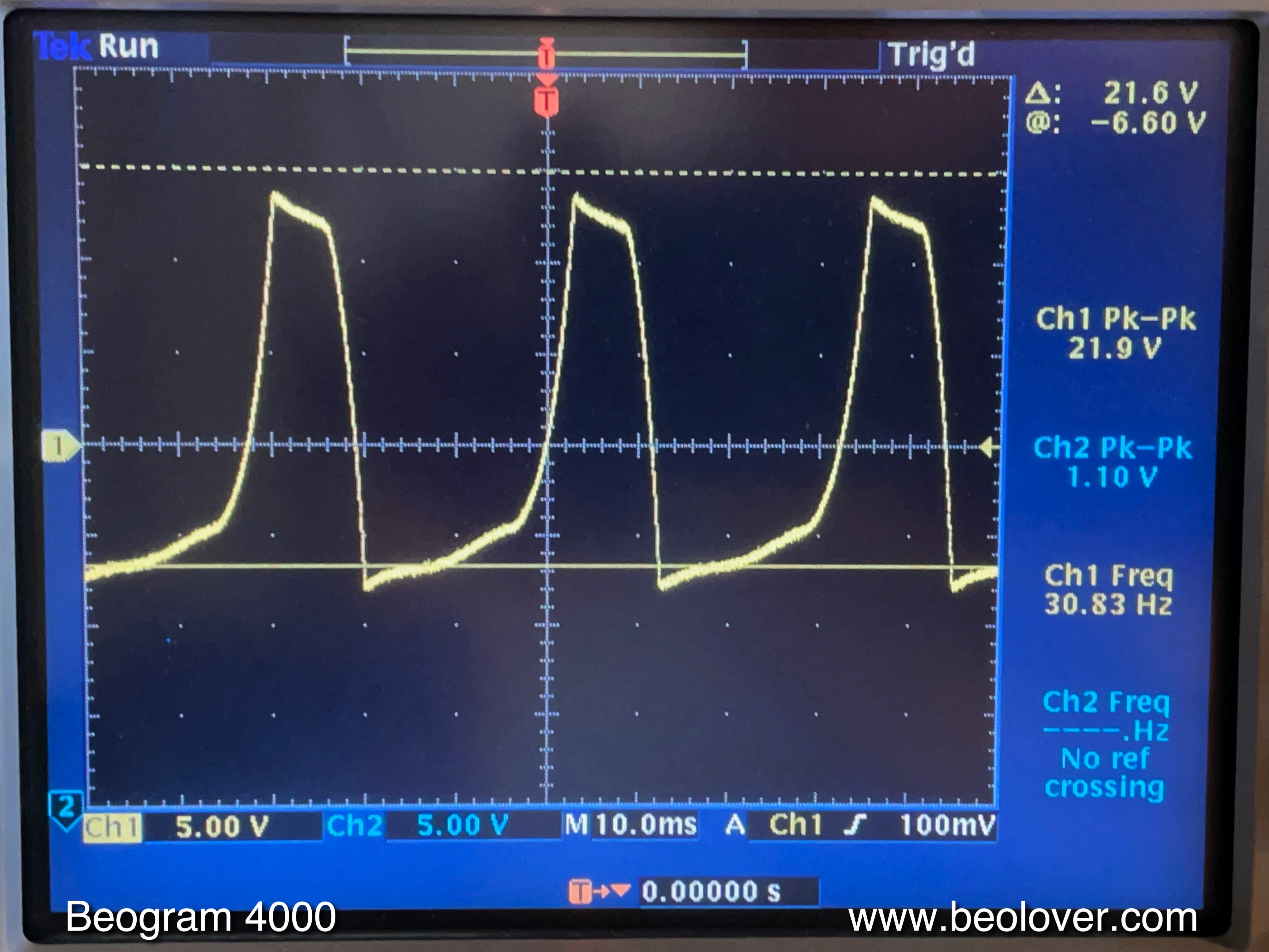
These are the motor voltage signals that I was able to achieve:
This is 33 RPM
and this 45:
All nice and good so far, but the ultimate test of any modification of the platter drive is to do a 24 hrs RPM test with the BeoloverRPM device. It allows logging the RPM in 10s intervals for extended periods of time:
The read trace is the one I measured:
For comparison I added the blue trace that was measured on a Beogram 4000 that I restored a while ago, and that still has the original bulb setup under the hood. Both curves look pretty comparable, both in their overall RPM stability and their short term RPM variations.
It seems this Wien bridge oscillator is back in business! On to finishing up this lovely Beogram 4000!


No comments:
Post a Comment
Comments and suggestions are welcome!