Featured Post

Beolover SyncDrive: DC Platter Motor Replacement for Beogram 4002 and 4004 (Type 551x and 552x)

Late Beogram 4002 and the 4004 (Types 551x and 552x), which have DC platter motors instead of the earlier synchronous AC motors usually suff...

Showing posts with label oscillator. Show all posts

Thursday, June 2, 2022

Beogram 4000: Choppily Rotating AC Platter Motor - Repair of Wien-Bridge Oscillator Circuit

The Beogram 4000 that I am currently restoring is a unit that 'keeps giving'!...;-). After restoring its tampered with sensor arm insert, I had to realize that this unit also had a defunct oscillator circuit for driving the AC platter motor. This was a first for me. So far there were never issues with this circuit in neither AC motor 4002s nor 4000s. Although I always wondered how long the light bulbs would last that are in charge of the 'automatic gain control' (AGC) of this circuit. Since the bulbs do not light up when the motor runs, I had high hopes that they would last much longer than bulbs that are in charge of lighting something up. The lower operational temperature should make the bulbs last for a long time. But not in this Beogram. I guess there are still mechanical vibrations etc, especially during shipping, that can damage these bulbs.

Anyway, the way I realized that there was an issue was that the platter motor ran 'choppily', i.e. the rotation was not smooth and I could visibly see a step-like, intermittent motion.

I hooked up the oscilloscope to the test point between the coupling capacitor and the phase shift capacitor of the motor (as defined in the manual for checking the motor signal). A sine wave is to be expected at this point when everything is working normally. Not in this case:

This looked more like a square wave than a sine! The next step was checking the signal at the output of the Wien oscillator at the collector of TR8:
This looked pretty similar, i.e. the issue had to be located in the oscillator. Strange signals at the motor capacitor can also be seen if one of the transistors of the push-pull stage is dead, i.e. this measurement was a necessary next step.
Ok...this meant a new and exciting territory of my Beogram 4000 explorations had been 'entered'! I never worked on the oscillator so far. So the first step was understanding how it really works. I poked around a bit on the internet and there are many resources, but often not very satisfying. Understanding oscillators can be a bit tricky, especially if you do not like to just believe mathematical deductions and 'electrical engineering lingo' wisecracks by experts who spend most of their time in complex number space. A pretty decent discussion can be found in an application note by Ron Mancini, a Senior Application Specialist at Texas Instruments. While he also tends to use EE lingo, he also throws in some useful morsels for the less initiated. 

Here is my interpretation of the Wien Bridge Oscillator subject:

After reading up a bit I made my own simulation in iCircuit. Before diving into the confusing circuit diagram of the actual two-transistor design of the Beogram 4000, it is helpful first studying the modern opamp based version of the circuit. It is much easier to understand. The operational principles are exactly the same as those employed in the Beogram circuit. Here we go:

Let's first remember the basic properties of an idealized opamp: 1) It is a differential amplifier that amplifies the difference in signals on + and - inputs. 2) Its gain is infinite without a feedback loop. This means that without feedback the output will be driven into the + or - voltage rail with only the smallest voltage difference between the inputs. 3) It is infinitely fast, i.e. the output reacts instantaneously to changes at the inputs.
So what is hooked up to the inputs of the opamp in the above 'Wien bridge' configuration? We see a standard feedback voltage divider hooked up to the "-" input comprised of RF and RG that basically gives this opamp a non-inverting gain of slightly larger than 3 (if RG were 1k then the gain would be exactly 3). 
On the "+" input we have a bandpass filter configuration (comprised of 1.2k resistors and 10uF capacitors in my example) arranged in a series and a parallel way. This filter can be considered simply as another voltage divider between the serial and the parallel sections, albeit one that is frequency dependent. 
I simulated the filter in LTspice that I was able to see a frequency sweep of the divider point between the serial and parallel legs:


I read off the diagram that the peak of the curve is at 12.5 Hz for the R and C values shown in the above circuit. The amplitude is at about -9.5dB, which corresponds to a 3:1 ratio between input and output (at divider point) voltages (dB=20log(Vout/Vin)). We also see that the phase shift at this point (dotted faint curve) is 0, i.e. the signal is in phase with the RF/RG divider. This means that for the peak frequency, this filter behaves like the exact opposite of the RF/RG gain voltage divider. 
In other words, at the peak frequency the opamp circuit is fed with 1/3 of the output signal at the + input, while the RF/RG feedback makes sure that it is amplified back to the original output voltage with a gain of 3. So we have a circuit that has a total gain of slightly larger than one (due to the 990Ohm value of RG). 

Here it is important to realize that at all other frequencies above or below the peak frequency this circuit has a gain of less than 1, i.e. any signal will die down to 0 if not stimulated externally somehow. The only signal that can 'survive on its own' in this circuit is one that has the peak frequency, hence we have a circuit that can only contain a signal at the peak frequency. In other words we have a precision oscillator that runs at a an exact frequency defined only by the R and C values in the filter circuit. Perfect for driving a synchronous motor at a fixed frequency!

How do the oscillations get started?

However: How does the oscillation get started? At the beginning, when the system turns on, there is 0V at the output of the opamp, i.e. both inputs are also at 0V, the other possible steady state of this circuit outside the RC defined oscillation. No signal is also a signal! 
Luckily, there is Johnson (thermal) noise in any circuit. This means there is a very small signal at the output of the opamp, even absent any input signal. Unfortunately, since the circuit has at best a gain of 1, such a small signal cannot be amplified into something bigger! 
And that is why this circuit needs to be designed with a slightly larger than 1 'best case gain'. This is achieved by the 990Ohm resistor (instead of 1k) in the circuit above. This causes the circuit to filter out any noise oscillations from the Johnson noise that are in the vicinity of the peak frequency, and to amplify them!
This amplification process will stop when the amplitude of the oscillation reaches the rail voltages of the opamp, where the gain will go below 1 for any signal. In the simulation above (yellow is the output signal) this 'end point' is 60Vp-p since I setup the opamp with a ±30V supply. 

The problem with the 'set it to a gain larger than 1' approach is that the band of frequencies that can be amplified broadens the more the gain goes above 1. In the above Spice simulation, the response of the RF/RG voltage divider would be a horizontal line, that would tangentially touch the top of the RC curve. As the gain of the opamp increases above 1 the line would not tangentially touch anymore, but rather 'slice' through the top of the curve. The two cutting points would define the frequency range that could be amplified.
In a nutshell this means that the output signal of the oscillator would contain no longer a single frequency, but rather a range of them around the peak frequency. This in turn would result in a distortion of the sine wave coming out of the oscillator.
So how do we go about if we want an oscillator that can start up easily without taking too much time, while having a nice undistorted 'pure' sine wave at the output when the signal is steady state?

Automatic Gain Control (AGC) for easy startup of the oscillator while maintaining a narrow frequency spectrum at the output:

The answer to this question is to make the RF/RG divider in a way that its gain depends on the output voltage, i.e. that for small signals it has a gain larger than one, and for the desired voltage of the output signal a gain as close as possible to one, but still slightly larger to account for 'worst case manufacturing outcomes', i.e. to compensate for component tolerances to make sure every oscillator will work.
The classic way (and therefore in the early 1970s design Beogram 4000) for AGC has been to use a small lightbulb for RG. Lightbulbs have the fortuitous property that their resistance depends proportionally on the temperature of the filament, which in turn depends on the current through the bulb or the voltage applied to it. This is perfect for our oscillator issue: When the signal is small the bulb will have its smallest resistance, i.e. the gain of the opamp will be highest. Once the voltage at the output goes up the temperature of the filament increases and so does the resistance. 
If the lightbulb and RF are selected matchingly a precise oscillator can be designed that also has good start-up properties.

Discussion of the transistor based oscillator circuit in the Beogram 4000:

A glance at the circuit diagram in the Beogram 4000 manual shows that there is no opamp in the design. The oscillator rather uses two transistors for amplification. The diagram from the 4000 manual is not very clear for understanding the circuit topology. I recreated it in iCircuit in a more streamlined form without the complicated 33/45 switchover circuits and the relay etc:

Ignore for now the 6 diodes on the left side. They take over the ACG action from the light bulb. More about this below.
The rest of the circuit reveals the same two voltage dividers like I showed above on the opamp inputs (all given component numbers refer to the 33 RPM setting): The band pass filter is composed of R8/R9/4VR1 and C4, and R121/VR1 and C1.  4VR1 is the 33 RPM trimmer in the keypad cluster, and 1VR1 is the 33 trimmer on the circuit board.
The RF/RB divider is composed of R8 and IL1 (the light bulb replacing RB for AGC purposes). I replaced the bulb with a trimmer in the circuit so I would be able to play with the resistance value while the simulation was running. I ended up setting the trimmer to ~50 Ohms for a speedy startup of the circuit. The simulation curves correlate in color with the ones shown above for the opamp model. Note that they were generated with the diodes in place. So, what are the diodes doing for us in this circuit?

Automatic Gain Control (AGC) with clamping diodes:

The I-V curve of a silicon diode shows that the forward current is very low until the voltage gets close to 0.6-0.7V. This is the voltage at which the p-n junction becomes conductive as the electrons gain enough energy to overcome the p-n junction's built-in potential barrier. Basically, putting a diode in parallel to a resistor lets the resistor do its thing below 0.6-0.7V, and above it progressively reduces the resistance of the circuit. Sort of like what the light-bulb does, but in reverse. And much less linearly. After all a diode is a semiconductor device and not a resistor!
If you put N diodes in series across a resistor then the resistor can be a resistor over a voltage range that spans ~N*0.6-0.7V, i.e. about ~2V if one uses 3 diodes like I did in the above circuit. Putting a second set of diodes with reversed polarity across the resistor makes the setup compatible with both current directions, which is the case in an oscillator.
The action of the clamping diodes can be observed in the simulation curves: Vp-p of the filter output (red trace) is 1.9V. 
Let's see what happens if I take the diodes out of the circuit (by opening the switch that I designed into the circuit:

It is obvious that the Vp-p of the output increased to 8.13V (vs. the gain limited 5.77V of the previous simulation). In conjunction we also see that the voltages at the inputs are now higher at 2.6V. Note that the 8.13V are a result of having R19 in the circuit which limits the current that can go into the oscillator, i.e. the voltage balance relative to the 24V supply drops across R19. This means the oscillator went to the rail at its output, similar to the opamp circuit, which made use of its entire 60V range.
The most significant difference between the simulation with diode clamps and without, however, is the shape of the waves: The diode-clamped circuit has much more sine-like waves compared to the unclamped circuit, and therein lies the benefit of the AGC: Instead of brutally being cutoff at the voltage rail, the gain is more smoothly regulated down to below 1 when the diodes kick in with their I-V curve, which is steep, but not a step. Steps have the unhappy property that the frequency space of the signal gets populated with an infinite range of frequencies that distort the signal.

Bottom line: It is possible to replace the light bulb in the Beogram 4000 Wien bridge oscillator with a ~50-55 Ohm resistor and 6 diodes

Maybe one more point: Why is the diode clamp on the RF (R18) resistor and not on the resistor that replaces the bulb? That comes from the fact that the resistance across the diodes drops as the voltage goes up, while that of a light bulb goes up under the same condition. In order to get a gain reduction at high voltages we need to put the ACG feature on the other resistor in the feedback divider for a gain reduction at higher voltages.

Implementation of the fix in the Beogram 4000:

Let's see what happens when the rubber hits the road:

I removed the bulb:

A measurement of its resistance yielded 24 Ohms. This baffled me since I expected the bulb would be shot. However, when I hooked it up to my bench supply and gave it some volts, it briefly lit up and then went dark. I was able to repeat this a couple times and then the bulb was done. So I think it was 'intermittent', i.e. the filament disconnected under load and then reconnected as it cooled down. This may well explain the measured curves since a disconnecting filament would limit the gain like a switch.

On to implementing the fix: I took six 1N4004 diodes and built the clamping circuit

And then soldered it across R18 on the PCB. 
I replaced the bulb with a 100 Ohm trimmer:
After some trial and error (by watching the amplitudes of the motor voltages for 33 and 45 RPM) I ended up having to set the trimmer to 54 Ohm to get stable operation for both RPM. 
One particularity of the Beogram 4000 oscillator circuit is that it has two RPM trimmers per speed. One in the keypad, that is user accessible and one on the PCB for setting the canonical RPM. A glance in the circuit diagram shows that the keypad trimmer corresponds to the R in the serial RC leg of the filter, while the PCB trimmer affects the R in the parallel RC leg. This is a problem for the oscillator, since it only has 0 degree phase shift when both RC legs have the same values. This means that in adjustable oscillator designs the two resistances are typically set by a double gang potentiometer, i.e. they are changed in tandem, keeping the oscillator in phase. If that is not the case, the gain of the oscillator needs to be set a bit 'stiffer', i.e. higher to guarantee that the oscillator will work in all situations. I learned this the hard way, when I adjusted everything perfectly for 33 RPM, and then tested 45 RPM the motor died down due to a too small oscillator amplitude. Only after reducing the trimmer resistance a couple Ohms the system started firing on all cylinders.

These are the motor voltage signals that I was able to achieve:

This is 33 RPM
and this 45:
All nice and good so far, but the ultimate test of any modification of the platter drive is to do a 24 hrs RPM test with the BeoloverRPM device. It allows logging the RPM in 10s intervals for extended periods of time:
The read trace is the one I measured:
For comparison I added the blue trace that was measured on a Beogram 4000 that I restored a while ago, and that still has the original bulb setup under the hood. Both curves look pretty comparable, both in their overall RPM stability and their short term RPM variations.
It seems this Wien bridge oscillator is back in business! On to finishing up this lovely Beogram 4000!


Wednesday, February 7, 2018

Beomaster 8000: Replacing the Processor Crystals

A Beomaster 8000 that I restored a few years ago for an Australian customer unfortunately had to come back to my bench due to a malfunction of the processor board. It exhibited rapid-fire power on/off events, which are a sign for a dead crystal on IC4 (slave processor). See here for more detail on how I first ran into this issue on the 8000 that is in my living room. Anyway, here are a few pictures of how I fixed this one. This shows the original setup:
As you can see someone in the past soldered jumper wires directly to the pins of the microcontrollers (savages!) to bridge the often failing vias that connect some of the processor pins to other components on the board. I usually re-solder the vias instead of putting in jumper wires. The reason that these vias fail is poor initial soldering. In the 80s electronics manufacturing just started becoming fully automated and some outcomes were not as high quality as one would desire...

Anyway, here I had to deal with these wires since it is good practice to take the microcontrollers out before replacing the crystals. They can be charged with high voltages when you take them out of the packaging, and this can fry the ICs...and that essentially would mean that a donor Beomaster 8000 would need to be procured. I was able to remove IC3 (right) without trouble but IC4 on the left was stuck. When the wires were soldered on a lot of solder was used and some of it penetrated the lower regions of the socket. I unsoldered the affected legs of the socket and then pulled the IC out. It came out including the three soldered-on pins from the socket. Once it was out it was easy to clean the pins up since I was able to get to the solder without having to heat everything for a dangerously long time...much better for the survival of the precious IC.

I implanted a new IC socket
And then exchanged the crystals and oscillator capacitors (the original ones are 12 pF while the modern crystals need 18 pF caps):
I elected to not solder the jumper wires back on to IC4. Instead I fixed the vias. I left the wires on IC3 in place since every time one heats up a pin on an IC there is a slight chance that damage can occur...

Once it was all back together, I fired the Beomaster up for the first time, and it came on normally, no more relay rattling etc...so I hope this did the trick.
Beolovely!


Saturday, March 11, 2017

Beomaster 8000: Microcomputer Board Reworked

Today was the day to work on the Beomaster 8000 microcomputer board. On an earlier post I noted that this Beomaster is an earlier model unit so it has the first generation Beomaster 8000 microcomputer board. The later model boards are direct replaceable but are definitely different. I will show an example of the late model microcomputer board at the end of this post.

One thing I don't like about these first generation boards is the metal enclosure around the processor ICs. It is necessary for shielding of course but these early boards are difficult to open up. B&O soldered metal tabs to connect the upper and lower sections of the metal shielding box. The problem is the tabs also solder to the ground plane of the the microcomputer board. Because tabs are soldered to the ground plane a lot of heat is required to melt the solder for removal. When people try to open the shield box up to get to the components they usually damage the traces on the board where the shield box mounts to it. This Beomaster has been serviced before and falls into the category of having damage to the mounting points.

The following picture shows the two different Beomaster 8000 microcomputer boards. The board for this project is the bottom board. Notice that the metal shield box on the top board is pressed to fit while the bottom board is soldered together (red circles show some of the solder locations).


Here is the microcomputer board for this project as it was before restoration.


Here are the covers removed.


The early model boards used a metal bar for a heatsink on the two main processor ICs (IC3 & IC4).
The places circled in red show the damaged places on the board where the mounting tabs for the case originally were. The last person to work on this unit was able to re-seal the box with solder but I won't want to do it that way again as I don't trust the grounding with those missing tabs.


This is similar to what B&O used in the metal shield box for the Beogram 8000 and 8002 turntable processors. A strip of special tape is used to keep the messy thermal paste off the ICs themselves.
Here is the component side of the board with the thermal tape removed. The restoration task will be to replace the 22uF electrolytic capacitor to a 105°C, high reliability type. Also the 1uF tantalum. Following Beolover's lead I will also replace the two oscillators for the processor ICs (X1 & X2). Those will require changing two capacitors on each to new ones that match the new oscillators (18pF). Last, I will also reflow the solder joints on all of the connects and board vias as those have been known to have hidden problems.


For the oscillator capacitors, this original board has two 12pF capacitors for each oscillator. One oscillator has its two 12pF capacitors on the component side. The other oscillator has them on the trace side. 


The later model microcomputer boards have mounting holes for the oscillator capacitors on the component side.

Here is the microcomputer board with its updated components.

CAUTION: As Beolover noted in his Beomaster 8000 restoration, messing with the crystal oscillators could be a risk to the two processor ICs (IC3 & IC4). As a safety measure I shorted the two oscillator leads together and removed the processor ICs from their sockets (using an ESD grounding strap of course). With IC3 and IC4 safely out of the way I performed all of the rework to the board.


After doing the tedious solder reflow work it is time to put this board back together. I re-inserted IC3 and IC4, then prepared the heatsink thermal tape and compound so I could remount the top and bottom covers.


Now to solve the broken ground points where the metal covers mount. I have solved this problem before by using copper tape the way metal bands are wrapped around crates for shipping. The copper bands fit perfectly in the board slots where the mounting tabs go. I solder the bands together on the top and bottom of the metal box. I also solder the copper bands to the metal box so the grounding will work as it is supposed to. To tie the box to the board ground planes I run a copper tape strap to the main ground lug (both on the top and bottom side of the board).

The result is not the prettiest thing (rather ugly really) but it is solid and works. The copper straps securely keep the box together and I can measure good ground continuity anywhere on the board. If I have to do this type of repair again I think I will apply strips of copper to the lid pieces first (to use as solder pad anchors if you will), then tie the bands in with those anchors.


Removing the assembly should be pretty easy.  I didn't solder the copper straps on the sides where the top and bottom pieces meet. To open this box up again I only have cut the straps along the sides, de-solder the two main ground straps and the box will open up. In the picture below I marked the cut points with the red arrows. Note the green arrows. Those show the previous repair where someone fixed the broken ground connection by scraping away some board coating at the ground plane and soldered that right to the metal housing. While that should work I think it is risky because it is susceptible to the solder joint cracking if the metal box is stressed. I like the straps better because they provide a much more reliable connection to the ground plane of the board. The grounding strap also has a little give in it so it can withstand any movement.


Now it is time to test this updated board in the Beomaster 8000. 
I am happy to say that works great. Now it needs exercising for a while to make sure there aren't any hidden problems.


For reference - Here is a Beomaster 8000 later model microcomputer board I restored earlier.


These cover plates are easy to remove as they just press-to-fit. Not the rectangular tabs in the top cover plate. Those make contact with the two main processor ICs (IC3 & IC4) to transfer heat away from the ICs and to the metal shield box for disapation.


Here is the component side (restored). Both sets of 18pF capacitors for the new crystal oscillators are on the component side of this board.  Also notice that this board has a frame for the top and bottom covers permanently mounted to the board. This frame provides all of the structure. There is no strain on the board layers and no soldering of the shield box. Way nicer for servicing.


Here is the trace side of the board. All I did on this side was reflow solder joints.


Now I need to get back to the assembly of those Beomaster 8000 display modules so I can complete the last board.

Friday, October 7, 2016

Beomaster 8000: Rattling Main Relays and a Broken 2MHz Oscillator Crystal

*********************************************************************************
ACHTUNG: Please, note that the crystal exchange procedure described here can damage the microprocessor chips on the uProcessor board. It is recommended to remove the chips before replacing the crystals and the capacitors. Due to the inherent capacitance of these devices, high voltages can be present between their terminals, which upon release, can burn out the gate that forms the oscillator together with the crystal. Make sure you short circuit the leads of the parts before installing them.
*********************************************************************************


Oh well, nothing lasts for ever!...The fully restored (2011) Beomaster 8000 that I am using in our living room recently broke with a rather strange fault. I woke up at 4 am in the morning to the beeping of an uninterruptible power supply (UPS) in distress. First I thought we had a power outage, but it turned out that the UPS turned itself off due to a malfunction in the connected Beomaster 8000 (I run all my B&O equipment on UPSs to reduce the risk of damage from grid voltage spikes and the like). I restarted the UPS and immediately the main transformer power relays of the 8000 started going on/off in rapid sequence. And then the UPS caved in again, turned itself off and started beeping again. This immediately pointed to a severe fault in the 8000 since a UPS only shuts down if the current drawn exceeds the rated 10 or 16 amps. This suggested to not try running the Beomaster again before having a look inside.

I shut everything down and went back to bed. The next morning I swapped the 8000 out with one of the other 8000s I have around the house in less important locations. A few days later I opened the malfunctioning unit up and ran it. First everything was normal but after a while it started to rattle again. I switched it off immediately and started wondering what might cause such behavior. First I thought there is a problem in one of the outputs triggering the protection circuit. The reason was that I initially detected 15V at the output of the protection circuit (collector of 6TR15) during relay rattling phases. The 15V pull up the base of 6TR11 via 6D12, which then causes the relays to go off, cutting power to the main transformer. This is usually caused by malfunctioning output transistors or overheating of the outputs. However, in this case the 15V were rather a consequence of an entirely different root cause.

After some playing around with the unit and enjoying a few more UPS shutdowns and relay rattling events, I finally figured out that the crystal oscillator of 9IC4 on the main processor board had some issues. I figured this out due to two phenomena:

1) After one of the rattling episodes I was not able to turn the Beomaster back on. The standby LED was lit, but no more reaction to the keypad. Panic ensued since I thought I had accidentally fried the processor or some other disastrous event occurred. So I did a processor self-test by pressing the Monitor key first and then additionally the on/off bar on the keypad. This initiates a self-test sequence. And I finally saw my first error code on a 8000: TE8!
The manual yields a rather cryptic cause for this error:

"Error TE8:    Defect IC:9IC4(RAM)      Or short pin to chassis: 10-11"

Initially I thought I had really fried the slave processor that is responsible for the relays...but then ,after my initial panic subsided and normal brain functions kicked back in, I thought that my maxim "silicon usually dies last" should apply here too, since even a complete main power supply failure and dramatic short circuit etc...would have a hard time killing anything on the processor board. There is simply no direct connection. Furthermore, when I tried to turn the unit on again after an hour or so, it worked normally again indicating a healthy state of affairs on the processor end of things (silicon either is alive or dead...rarely there is an intermittent state in my experience). Also, once it worked again, the error code went away and I got this from the self-test:
A happy Test Passed (TP).

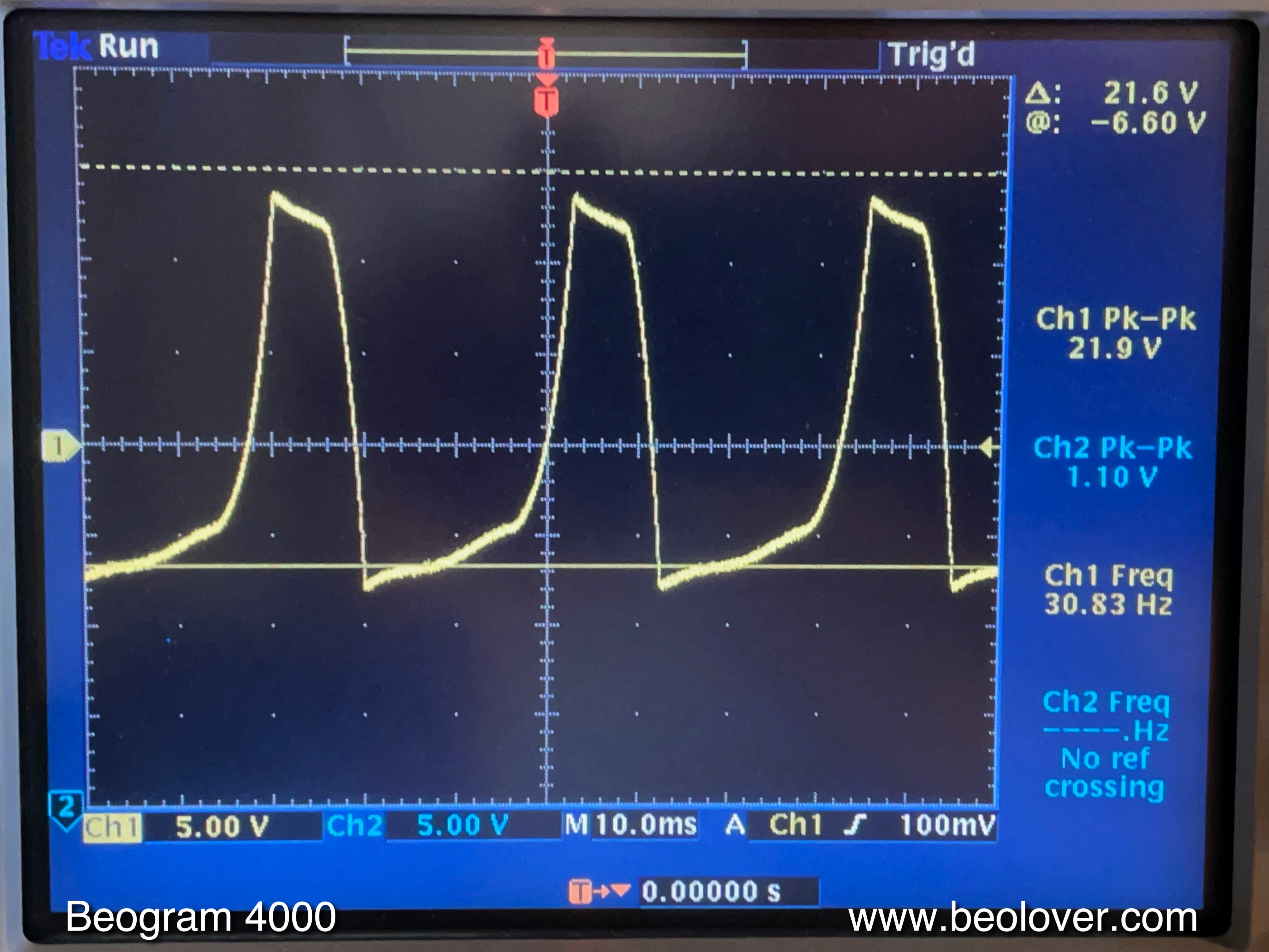
2) The second indication toward the oscillator issue came from an oscilloscope measurement I made after the error code episode:
The probe was hooked up to the base of 6TR11, which is connected to Pin 16 of 9IC4 via some resistors. At this point the unit was working and there was no rattling from the relays at all. But you see some type of digital random oscillation of the signal that normally should be just near-0V when the unit is on. The digital character of the signal already suggested to me that there might be a processor issue...I watched this for some time and then it changed to a more aggressive behavior:
A much stronger deviation from 0V and still pretty random and close to switching 6TR11! And then it went completely crazy and the relay clicking started again as 6TR11 did its job. I did not save the measurement at that point since I was busy turning off the unit as fast as I could...;-). This finally put me on the right track, however, and I started looking into 9IC4. The same random signals were also directly visible at Pin 16 of 9IC4, just on a 0-5V scale since at Pin 16 we are directly at the source of the signal and there are no resistors over which the voltage drops. This told me that indeed the processor was going 'crazy' occasionally. This combined with the error information above that alternatively to a processor malfunction also Pins 10-11 could be 'grounded' finally made me see the light since the oscillator crystal is connected to Pins 10 and 11!

I wiggled the crystal a bit and indeed, I was able to cause the Pin 16 signal to change from completely quiet 0V to the above shown random signals and to 'crazy' causing relay rattling. So I guess what happened was that the clock of the processor started to have random hiccups causing timing issues while processing its firmware, which then caused the normally constant output at Pin 16 to become random triggering the relay circuitry.

I ordered a few 2MHz crystals from Newark (21M6819) along with matching 18pF resonator capacitors (46P6436) - the original crystals run on 12 pF capacitors, i.e. they need to be exchanged along with the crystal to get a proper oscillator signal. After a few days I received the parts and put them in. This shows the original crystal with the two capacitors (brown, right below):

This shows the board with the parts removed:
This is the new smaller crystal in comparison to the original one:
Like most components modern ones are considerably smaller than the original ones...and this finally shows the new units implanted (I also exchanged the 9IC3 components assuming both the original crystals were from the same batch...;-):
The exchange is straight forward, but the right capacitors are difficult to remove since one of their legs is fed through a hollow via, which is a bit of a pain to unsolder due to the very small space between lead and via insert. One has to hold the solder tip to the via to liquefy the solder and then pull the cap out...three hands would be great for this process...;-)

One more thing: It is crucial to cut the leads on the solder side of the board very short to prevent short circuits to the EMI can that encloses the processors:
I had them too long initially, and I got some really spectacular readings on the displays when I turned the unit on. Essentially, it became completely unresponsive showing some random zeros on all of the displays. Another near-heart attack...;-). Cutting the leads solved that problem...live and learn...;-) 
I am running the unit now for a couple days back in the living room and it seems the issue has gone away. Also wiggling the crystal did not cause the issue anymore. So I am assuming we are back in business with this lovely Beomaster 8000!

Remarkably, a few days after this happened to my 8000 I received an email from an Australian customer whose 8000 I restored a couple years ago telling me that his Beomaster developed the exact same symptoms (I am sending him a couple crystals and the capacitors plus some instructions...this is Beolove!).
So I am thinking that exchanging the crystals should become a standard part of any Beomaster 8000 restoration...two at the same time is a rather strange coincidence, which points to a systematic issue with these crystals. Probably the leads are delaminating from the crystal material after 30-35 years...
Time to get back to my other restoration projects!