********This unit is currently for sale. Please, see here.*******************
This post describes the complete restoration of the Beogram 4002 (5513) from Arizona that I initially assessed here. This shows the unit as received:
As usual, my first step was starting the platter motor bearing oil infusion. This shows the extracted motor:
I disassembled it to get the bearings (two small donuts on black pad) out:
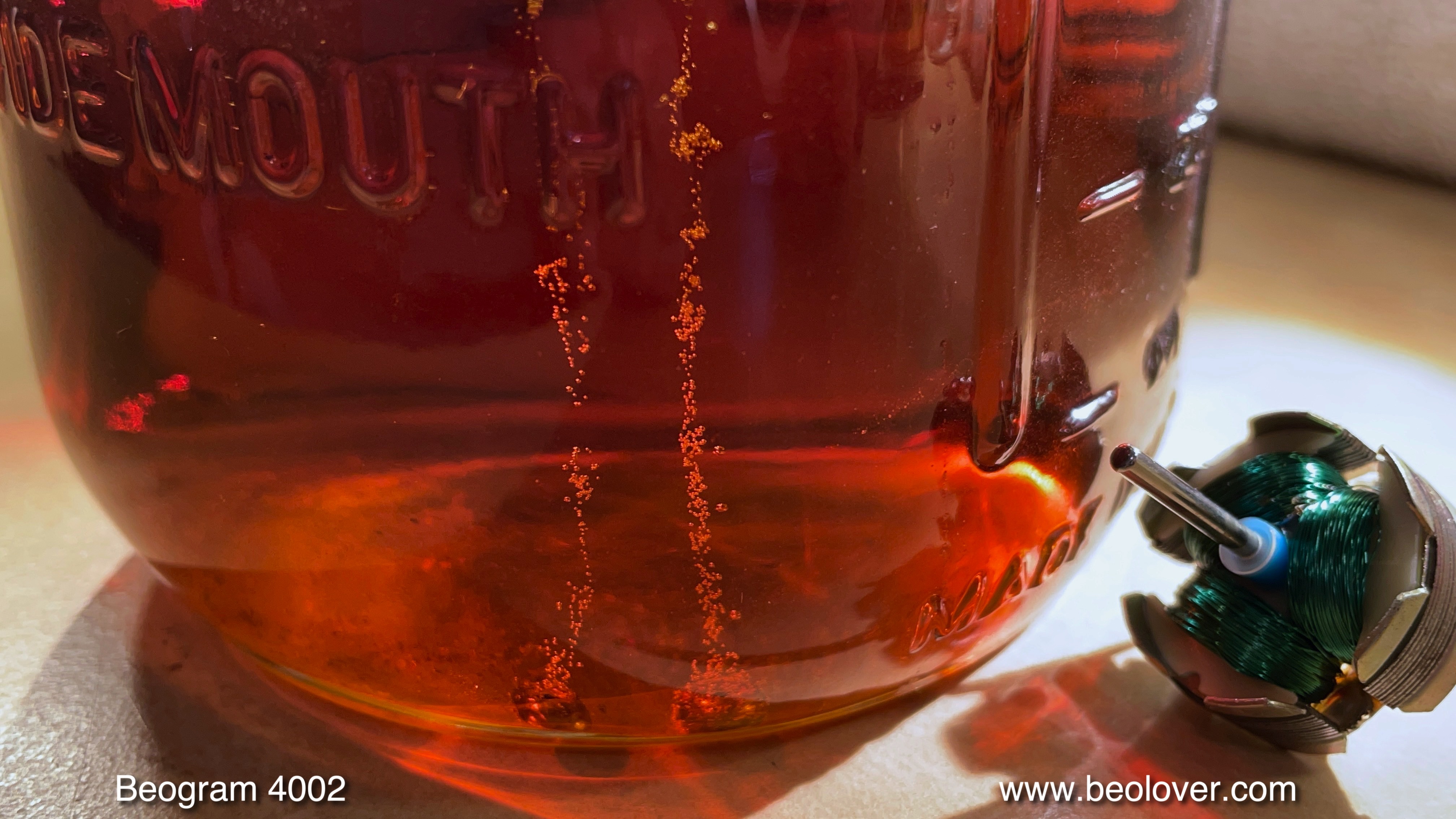
Then I immersed the bearings in motor oil and pulled a vacuum. Immediately strong bubbling started as the air was drawn from the porous emitted bearing material, making room for fresh oil to interdiffuse back into the material:
While the infusion process was taking place (usually takes 2-3 days until the bubbling stops), I removed the moving parts of the arm lowering and carriage transport mechanisms for cleaning and re-lubrication:
This shows the cleaned components:
After re-assembling the mechanisms, I replaced the cracked plastic carriage pulley with a machined aluminum replica:
Then I replaced the incandescent light bulb of the tracking feedback mechanism with a LED based replacement. The black box in this picture shows the original part in place:
This shows the replacement. The blue part is a trimmer that allows adjusting the intensity of the LED, which is useful for fine-tuning the tracking mechanism:
The final aspect of the carriage restoration was to remove the damper-to-tonearm linkage and lubricate its pivot point. For this one has to remove the sensor arm. This shows the arms assembly from the back.
I removed the sensor arm assembly
and removed the linkage
As usual the small copper plate that reduces the lateral arm friction when the arm is up was only loosely attached and fell off after a light tug:
Originally, it is attached with double sided tape, which after 40+ years is usually degraded. I epoxied the part back into position:
This concluded my work on the carriage/arm lowering mechanism. The next step was rebuilding the main PCB. A while ago I started replacing all the power transistors and Darlingtons on this board since I had a couple returns to my bench after one of these transistors failed. So it seems they are also affected by the aging process. That much for 'silicon is forever'!...;-). It is best to replace the two on top of the board while the board is still bolted in. This shows the original TIP107 Darlington that drives the solenoid, 1IC4:
I replaced it with a TIP107:
After replacing these devices, I removed the board. This shows the component side in original condition:
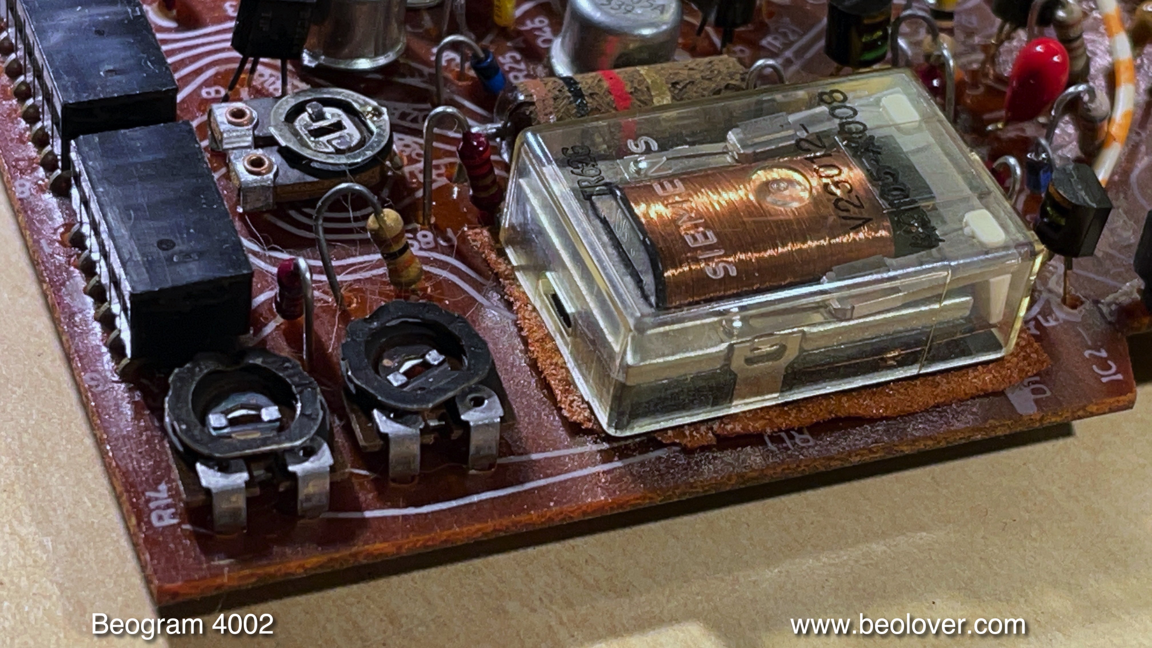
This is a detail shot of the original RPM section, consisting of the Siemens RPM switch relay and the two RPM trimmers for tuning the platter speed:
I exchanged all the electrolytic capacitors, the RPM section, and the sensor arm circuit, as well as the transistor that supplies the platter motor with power:
This shows the rebuilt RPM section. I use 25 turn encapsulated trimmers. This allows a much more consistent adjustment of the RPM:
The next step was rebuilding the output board, which houses the output relay and the delay circuit that makes sure the relay only triggers after the needle has safely landed in the groove:
This shows the rebuilt board. I also installed a (red) switch that allows connecting system and signal grounds in case there is a hum issue.

My next focus was on replacing the degraded transport lock bushings:
This requires removal of the floating chassis so one can vacuum all the fragments out of the enclosure. They can impede the floating chassis movement when they get stuck underneath. Due to the elegant flatness of the Beogram design there is not much room for the chassis to move. During this step it is a good idea to also remove the original reservoir capacitor:
This shows the emptied enclosure:
I vacuumed the enclosure and prepared the bushing replacements:
They are 3D printed. They install as a two-part assembly, where one half goes in from the bottom and the other from the top. this makes installation a snap. This shows one of the locks after installation of the new bushings:
Here a shot of the new reservoir capacitor assembly. This Beogram came with a two-capacitance unit since it is a CD-4 board ready design, where the CD-4 board has its own reservoir capacitor. These dual-capacitance units are no longer available, and so I replace them with two modern capacitors that are common grounded:
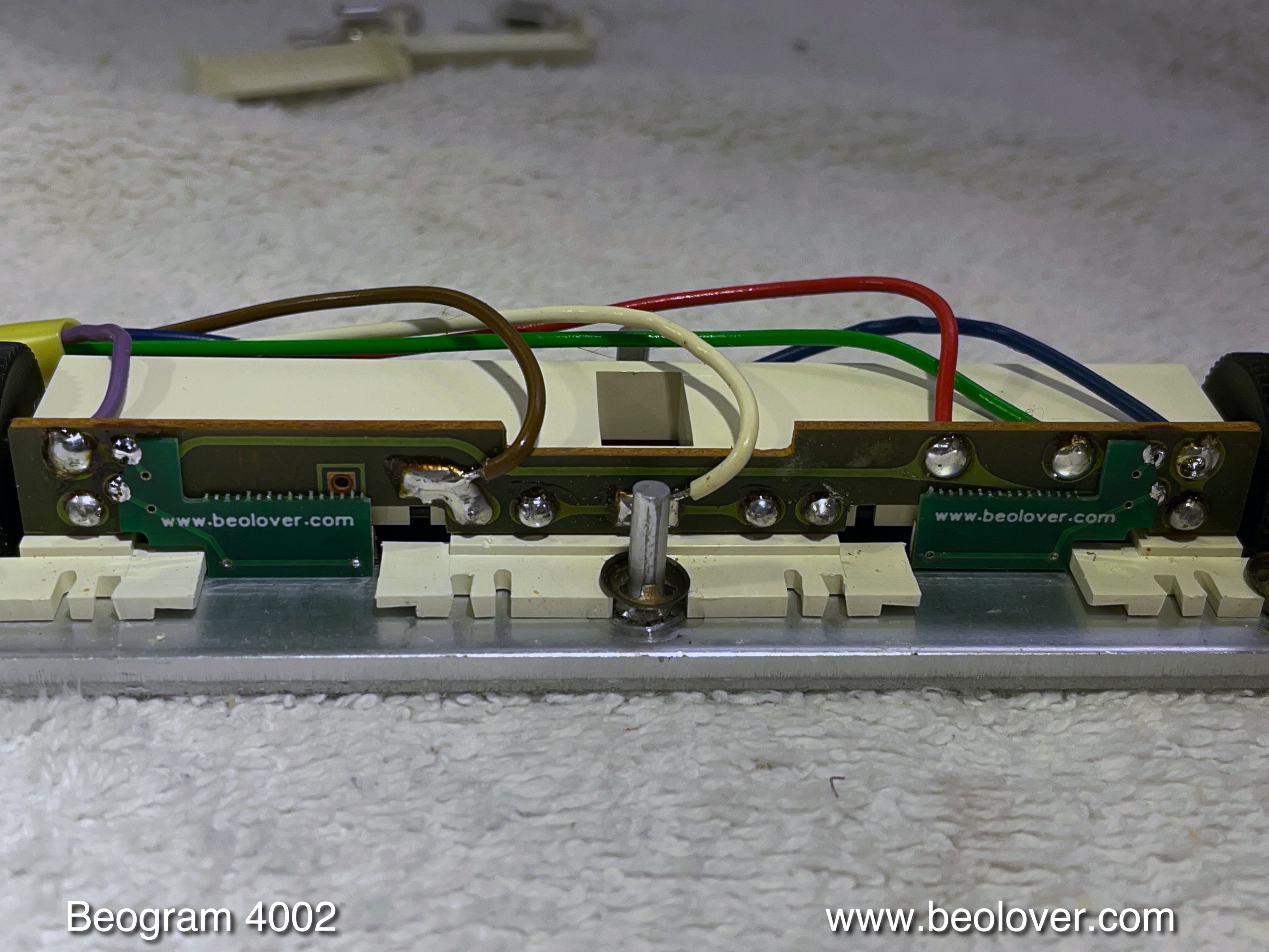
After this chapter of the restoration it was time to replace the remaining incandescent bulbs with LED assemblies. First I focused on the RPM panel. This shows the extracted panel with the original bulbs still installed:
These are the recently
updated LED based replacements:
They solder directly to the solder points of the original bulbs. Beolovely!:
This shows one of them in action:
The final bulb to replace was the one in the sensor arm. This shows the original bulb and the replacement:
I installed the replacement. This shows the LED in action:
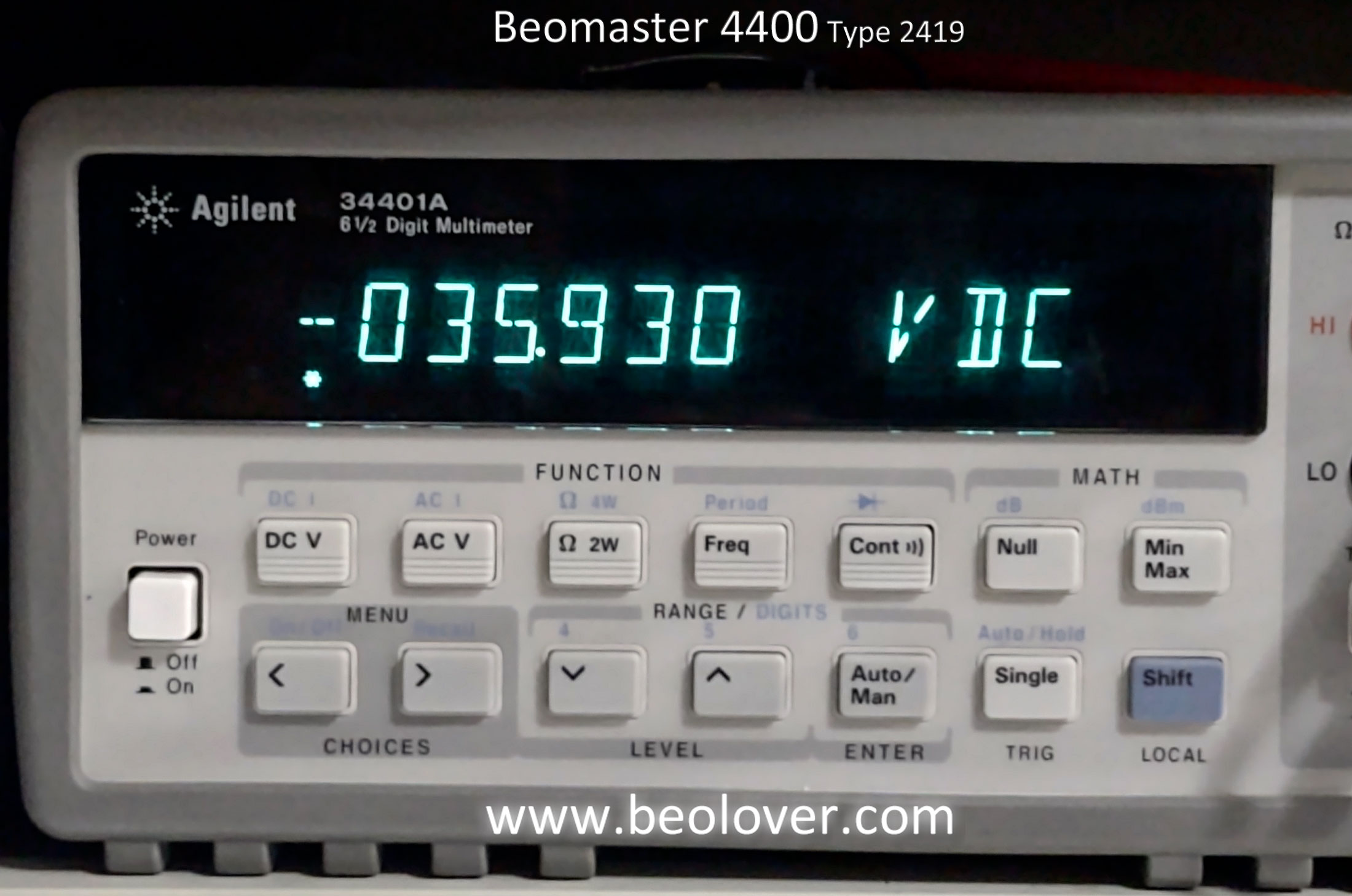
After replacing the light source in the sensor arm it is a good idea to check the sensor signal without a record on the platter. This is the trace I measured:
An amplitude between 4-6V is acceptable that the circuit functions reliably. This is important to protect the stylus from accidentally being lowered on the empty platter.
In the meantime the bearings had concluded their infusion process. I extracted them from the oil:
and reassembled the motor. Now it was time to measure the longterm RPM stability with the BeoloverRPM device:
It allows logging the RPM once every 10s for extended periods of time.
This is the curve I measured after about 24hrs:
This is about as good as it gets with the DC platter motors in Beograms!
A routine check of the fuses compartment revealed that one of the fuses was 'embellished' with some aluminum foil. Not something the Beolover would advise to do at home!
I installed new fuses.
This is generally a good idea, since many of the old glass bodied fuses have loose metal parts, i.e. the fuses are not sealed anymore. This can lead to corrosion and blown fuses without a real reason.
Now it was time to do the adjustments. After adjusting the platter height, arm horizontality and height, floating chassis position and platter centrality I focused on calibrating the tracking force. The first step is usually the replacement of the flimsy circlip that holds the counterweight screw in place
with a M3 nut, which allows fixating the counterweight in place that it can withstand the rigors of shipping without voiding the calibration:
Then I calibrated the weight scale to be accurate around the 1.2g mark:
After this I adjusted the arm lowering limit to make sure the stylus would miss the ribs on the platter in case of an accidental arm lowering due to technical malfunction of the control circuitry:
Another important adjustment is the tracking feedback, which makes sure that the carriage correctly and smoothly tracks the inward needle movement during record play:
At this point this restoration was coming to a close. The final technical touch was the replacement of the corroded original RCA plugs with modern all-metal units with gold plated terminals. This shows the original plugs:
And their replacements:
Beolovely!
The final steps of this restoration were cosmetic: This Beogram had rusty chassis springs:
My customer suggested to use Loctite 'Extend' rust neutralizer on them. I decided to get a jar of this compound and give it a try (these were not the first rusty springs that appeared on my bench). I brushed the neutralizer on the rusted areas:
After a couple coats and 24 hrs curing, I spray painted them with some matte lacquer. Definitely looks better than before!:

And now this Beogram does not only play like new, it also looks awesome! Perfect! I celebrated this moment with a recently acquired 'Return to Forever featuring Chick Corea' album from 1975, "No Mystery" (Polydor PD6512), which was of course ultrasonically cleaned with a
CleanerVinyl ProXL setup. Beautiful!:
After this successful test, it was time to fix the hood. It was badly scratched,
and so I used 220 grit sand paper to even it out before polishing it back. This is how it looked after the sand paper treatment:
Then I polished it back to translucency with ever finer grit. Once that was done, I repaired the degraded rubber bumpers
with 2mm O-ring snippets that I cut to 1 mm length:
These bumpers ensure a satisfying 'plop' sound when the hood is closed. Beolovely!
Here are a few impressions how this unit looked after the restoration:


.jpg)
.jpg)
.jpg)
.jpg)
.jpg)
.jpg)
.jpg)
.jpg)