Featured Post

Beolover SyncDrive: DC Platter Motor Replacement for Beogram 4002 and 4004 (Type 551x and 552x)

Late Beogram 4002 and the 4004 (Types 551x and 552x), which have DC platter motors instead of the earlier synchronous AC motors usually suff...

Thursday, January 27, 2022

Beomaster 4400 Type 2419: Diving into the Front Panel Switch Assembly

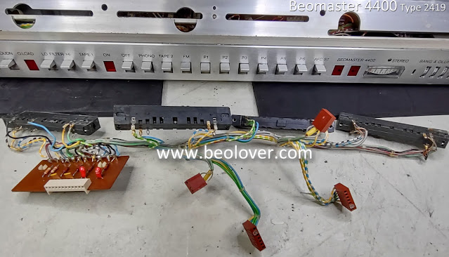
This Beomaster 4400 is opened up for restoration except for the front panel and the switch assembly.
My mechanical testing of the Beomaster switches shows there is a problem with the OFF switch where it is not disengaging selected source switches when the OFF button is pressed.

The way the switch assembly is supposed to work is for a press of one of the source switches to disengage the OFF switch and the Beomaster powers on.

When the OFF switch is already disengaged (power is on), then pressing a source switch disengages the currently engaged source switch and becomes the music source for the amplifier.

That functionality works.

Pressing the OFF switch should disengage any source switch that is pressed and the Beomaster power is turned off.  

The way this Beomaster's switch panel is operating now, the OFF switch will turn the power off but the selected source switch will remain engaged.

If a repair for this function wasn't possible it wouldn't be the end of the world as the Beomaster 4400 can turn off.  It would be a slight inconvenience though. For example, if you were listening to Phono and you turned the Beomaster off with the OFF switch, the Beomaster would turn off but the Phono switch would remain engaged. So if you came back and wanted to listen to Phono again you couldn't use the Phono switch to turn the Beomaster on (because it is already engaged).  You would have to press a different source switch to turn power on the Beomaster, that would reset the Phono switch, then press the Phono switch.

So I am going to try and get to the bottom of the problem with this switch assembly.

Here is the switch assembly as seen from the back and still installed in the front panel.


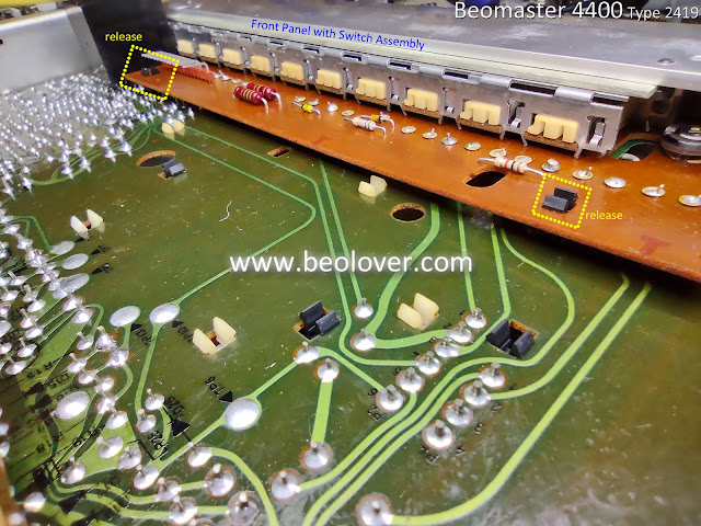
To get to those switches there are mechanical fasteners that have to be removed (screws) and electrical connections that have to be de-soldered.  Bang & Olufsen went with a lot of hard-wired connections in these 1970's era receivers.  That is actually good for long term reliable component to component connections...but makes it hard to work on :-).

In the photo above I highlighted two plastic clips that hold and stand-off PCB 5 to PCB 6.
Those need to be released.
PCB 5 is the main board in the Beomaster. Everything connects to it.
PCB 6 is one of two signal routing boards for the switches and display components on the front panel.

Next, I loosened four screws that secure the Beomaster 4400 transformer assembly and filter capacitor bracket to the front panel.  They have slots instead of holes so those pieces can just be loosened and the front panel pulled out.


Up next are four screws that attach the front panel to the frame.
Two are inside at opposite ends of the front panel.
You need a long, skinny screwdriver to access some of the screws on the Beomaster 4400.


Note the wires in the above photo.  Once the panel is loosened enough to pull out, those wires will prevent being able to pull the front panel all the way off so at some point in the disassembly they will have to be de-soldered.  There are too many wires to show a step-by-step de-soldering so just note that type of task has to be done at various places during the disassembly of the switch panel.

The other two screws are on the front.


The removal seems pretty easy so far but there is still a long way to go.

The next step is to do some de-soldering of some wires between the main board (PCB 5) and the switch assembly board (PCB 6).


The front panel should be able to be partially pulled away from the Beomaster 4400 at this point.
Wires from the various connections prevent it from fully coming off so those have to be tackled next.

The front panel indicator lamps need to be removed as well.
They pull off their mounting spades by carefully pulling them out. I use a small pair of pliers.


There is one indicator on the front panel, the stereo indicator, that is really a pain.
It is an LED and glued to the front panel.  So it can't be removed easily and can break.
But it has two wires to it that need to be removed.

My solution is to cut the wires for the stereo indicator LED far enough back where I will add a two pin connector later. 


In the past I have tried eliminating some front panel assembly steps by leaving the FM tuning dial assembly in place but that doesn't work out well.

It is much easier to get components out of the way.  There are parts of the dial assembly and the flexible wire routing ribbon that are delicate so removing them also protects them.
The FM dial assembly only has two screws to remove but it also requires some de-soldering.


The next step is to remove four screws that secure the actual switch assembly to the front panel.
Once that is done the front panel should be able to be removed.


Besides the two screws the above photo shows the result of my having to de-solder a number of wires from this part of the switch panel.

The front panel should now be free to remove from the Beomaster 4400 and the switch panel will be fully revealed (well, almost).


The power cable to the OFF switch must be removed to free that connection up.


This disassembly also provides easy access to the FM signal strength meter.
It has a lamp that I will replace.


The remaining disassembly tasks are mainly de-soldering tasks.
There is the flexible ribbon that goes from the FM preset tuning dials to the switch assembly.
It is very delicate and needless to say, you do don't want to damage it.


Then there is the PCB 6 wiring board. It is soldered right to the switch assembly so it needs to be removed to be able to get to the individual switches...my goal.


One side of the switch assembly is now fully accessible.

This is the other side.


Now I can finally tend to the switches themselves.
There was a lot of de-soldering to get here.  I think I had to clean my de-soldering gun twice during the process.

Here is one of the source selection switches (Phono switch) opened up.
The phenolic board with the contact posts slide between spring contacts in the plastic switch housing.
The phenolic board is fixed to the switch assembly frame with metal tabs.
The plastic switch is the part that moves.

One nice discovery about this earlier serial number Beomaster 4400 from the later serial numbers (that I am more familiar with) is that the tabs that secure the switches to the switch assembly frame are much longer here.  It is rather easy to open these up (once you get to this point).  On the later serial number Beomaster units the tabs are ridiculously tiny and terribly difficult to open up without damaging the tabs. 


Here is the switch problem with this Beomaster 4400 shown with the switch assembly removed.

The picture below shows the proper switch positions when the Phono source has the Beomaster powered on and the OFF switch is in the disengaged position (meaning power is on).


Pressing the OFF button to engage it will disconnect power from the power switch and should disengage the Phono switch.

Instead, the OFF button is in the off position but the Phono switch is still engaged.
Again, that doesn't mean the Beomaster would still be powered on. It will be powered off due to the position of the OFF switch.  But the Phono switch being in the engaged state will mean it cannot be selected to turn the Beomaster on again. It has to be reset to the disengaged position first.


I spent a lot of time next in operating the switches and observing how the mechanics worked.
I am convinced now that the problem is just in the action on the OFF switch as all of the other switches work properly.  They engage and disengage properly when they are used.
It is just the OFF switch that is not able to reset the source switches.
Except...Tape 1.  There is enough movement of the switch control bar to disengage the Tape 1 switch when OFF is pressed.

Looking carefully at the movement of the OFF switch actuator I can see that pressing the OFF button causes a small, plastic post on the actuator to push against a metal lever.  The lever has a wide section and when the post press against that the lever should move the switch control bar enough to disengage any source switches that are engaged.


In the case of this OFF switch I can see that the lever is not moving enough to cause any disengage activity on the switch bar.  I am able to manually press the lever a little bit more by hand and then everything worked properly.

I couldn't see any possible adjustments to make to correct the problem so I removed and inspected the OFF switch.
Interestingly I discovered a notch appears to have worn away on the small, plastic post that presses against the lever.


If it was not for that notched away section on the post there would be enough movement in the lever to move the switch bar correctly.

So that is where I will leave it for now.
I have to look at my options.
I can look for a spare OFF switch from another Beomaster 4400 of this type.
Later serial number Beomaster 4400 units are not proper donors because their switch assembly and power switch is different.  Beomaster 3000 and 4000 models are supposed to share this type of switch so that is an option.

However, I want to take a stab at repairing or modifying this actuator post so that it will work.
Maybe some well placed (and formed) epoxy.  I wonder if that would hold up to long term movement of the lever rubbing against it. 

Beolover suggested some PTFE tubing. That might work.  The post is 2 mm in diameter so I went ahead and ordered some PTFE tubing that has an inner diameter of 2 mm.  The outer diameter is 3 mm so I will have to see if that will work when the OFF switch is fully engaged and fully disengaged.

Here is what the post and lever positions are when the OFF switch is engaged.
A 1 mm border around the post might be too much.


Maybe I will have to cut away some of the post material and epoxy on a 2mm outer diameter PTFE piece.

More investigation on this ahead.

While I am waiting I can get started on the capacitor replacement tasks.

Tuesday, January 25, 2022

Beogram 4002/4004: Updated LED Assemblies for Replacing Incandescent Bulbs in the RPM Adjustment Panel

I recently re-designed the circuit boards of the LED assemblies for replacing the regular incandescent light bulbs in the RPM adjustment panels of Beogram 4002 and 4004. The main reason for the re-design was a manufacturer inconsistency in the red-green LEDs that I used in the previous version. This required occasional adjustment of the resistor values to maintain the 'incandescent looks' of these panels. At the same time warm-white LEDs have become much more ubiquitous in recent years, and so I decided to re-design the boards using such warm white LEDs. This shows the new assemblies:


I recorded a video that shows how to install them. Enjoy!:


Beomaster 4400 Type 2419: Opening up for inspection

I opened up the cabinet of the Beomaster 4400 to inspect the inside and begin assessing the restoration tasks further.

I know from other Beomaster 4400 projects that the restoration tasks will include replacing electrolytic capacitors, no-load current adjustment trimmers and cleaning slider controls. 

Here are the steps to opening up the Beomaster 4400 cabinet.
The screws to remove the top cover and the bottom plate are at the back and underside of the cabinet.


Bang & Olufsen mechanical engineers like designing minimal fasteners for their cabinet tops.
Their cabinets typically slide into some slots and a few screws secure everything.

On the Beomaster 4400 there are four screws in the back of the cabinet that do this.
With respect to the Beomaster oriented upside down and from the back here are the cabinet screws.

The two on the left...


...and the two on the right.
The bottom screw on the right is rather difficult to get to.  It requires a skinny screw driver.
That is probably why the screw is missing on this Beomaster.


The left side has both screws intact.

The top screw loosens to release a locking lever that can be rotated to an unlocked position.
This same technique would be used by B&O on their Beosystem 5000 components.
On those cabinets just two screws are used to secure a sliding cabinet latch at the rear of the cabinets.


The latch keeps the cabinet lid in place horizontally on the cabinet frame.
The smaller screw secures the top of the lid to the frame.

Here is the smaller screw removed.
There is a rubber washer on the original screw that has usually deteriorated or is missing by now.
This one is still partially intact.


With the four screws removed the cabinet lid can be slid off and removed.

The bottom plate of the cabinet is secured with six screws.  
Four on each side and two small screws at the rear side of the plate.

Here is the first look at the underside of the Beomaster with the plate removed.
It is very clean. That is probably because the underside is less likely for dust to settle on...but the really clean inside shows that this Beogram must have experience good storage conditions.
I don't see any sign of corrosion or mildew.

The preamplifier board is located here and I have outlined it in the photo.
I will be removing it to do the capacitor replacement on that board.


Here is the Preamplifier board removed.


Nothing out of the ordinary there.  Everything looks proper so the restoration task on the Preamplifier board will be to replace the electrolytic capacitors with new ones. 

I will discuss with the owner if he wants the tantalum capacitors replaced with new electrolytic or WIMA polyester capacitors.  I typically replace the tantalums with those other types but if the tantalums are still in good tolerance limits it is a valid option to keep them. 

Looking at the open top side of the Beomaster shows the inside to also be in great shape.
There is some dust and a little grime...that is typical and no big deal.  I will clean all of that up.

There are three removable components for the FM tuner in the photo that I have highlighted.
Those will be removed next.

The component outlined in green is the FM Front End (PCB 1).
The component outlined in blue is the FM IF Section (PCB 2).
The component outlined in yellow is the FM Stereo Decoder and Indicator Circuit (PCB 3).


The Front End is secured to the cabinet frame by two screws which have to be removed first.


The PCB 1 and PCB 2 components are attached by some soldered wires so the two components are removed together.
The antenna cable needs to be disconnected from the PCB 1 component.
PCB 2 has three jumper wires that must be removed and two black, plastic clips that must be released.
After that PCB 2 should be able to be carefully pulled from the main board (where it is attached by two onboard connectors).

The connection points are highlighted in the photo below.


Here are PCB 1 and PCB 2 removed (and still attached to each other).


The third component to remove is PCB 3.
It also has a couple of black, plastic clips to support it on the main board.
There are also three jumper wires from the main harness that need to be disconnected as well as two board connectors.


Here is PCB 3 removed.


The next area I disassembled for the restoration is the front, metal bar that holds the slider controls.
Those always require cleaning and a little lubricating.  But like this Beomaster 4400, there are typically some lenses that need replacing. 

There are four screws that mount the slider control bar to the front panel assembly.
Two are on the ends and are easy to get to.


The next mounting screw is from the inside but is easy to get to as well.

This one was really easy as it was missing.  I will replace that with a new one when I reassemble the Beomaster.


The last one is a little tricky.  
A thin screw driver has to slide between a couple of the Beomaster boards (PCB 9 and PCB 5) to get to the mounting screw.


One more detail must be released before the slider control bar can be removed.

The FM dial cord attaches to the tuning slider control. 
It is typically attached to the plastic control with some glue. Often the glue hardened to form a catch that can be pried off the plastic control.


Everything that attaches to the slider control bar is removed now and the bar comes off.


The next disassembly task is to remove the slider controls along with their wire harness.

With them removed it will be easier to clean them.

Looking at the slider controls for this Beomaster 4400 reveals that they are a different type than previous Beomaster 4400 receivers I have worked on.  These controls are mounted with a pair of metal clips and some double-sided tape.  This Beomaster unit is an earlier model serial number than other units I have seen.  The later model units change to a different slider that mounts to the control panel with screws.

Here is a slide control from this Beomaster 4400.


This is going to be a fun task reinstalling this type of control.

Here is the Beomaster 4400 with the controls and harness removed.


On the back side of the Beomaster 4400 I removed the four heatsinks that are for the output amplifier transistors.  The heatsinks physically attach to the transistors they protect by screws that also secure the heatsinks to the cabinet frame.

In order to have the main circuit board (PCB 5) free to move when I replace the capacitors I need the heatsinks removed.

Since the heatsinks have to be removed I always redo the thermal coupling of the transistors to the heatsinks.  I usually use SIL_Pads for the coupling instead of thermal paste.


Everything I have removed and examined so far on this Beomaster 4400 are things I always do on a restoration of this component. 

It is often enough. 

However, on this unit I know from playing with the front panel switches that there is some issue with the "Off" switch not resetting the selected source switch.

In order to investigate that I will have to disassemble the rest of the Beomaster 4400 front panel.
I always kind of dread that because it is a big job.  It involves desoldering quite a few wires as the Beomaster 4400 wire harness to the front panel involves a lot of hard wired connections instead of connectors.  I'm sure that was due to space the connectors would take up. 

It is a task that must be performed though. Not doing it will result in problems with the Beomaster 4400 operation so that would not be acceptable.

In the next post I will get started with the disassembly of the front panel.