I opened up the cabinet of the Beomaster 4400 to inspect the inside and begin assessing the restoration tasks further.
I know from other Beomaster 4400 projects that the restoration tasks will include replacing electrolytic capacitors, no-load current adjustment trimmers and cleaning slider controls.
Here are the steps to opening up the Beomaster 4400 cabinet.
The screws to remove the top cover and the bottom plate are at the back and underside of the cabinet.

Bang & Olufsen mechanical engineers like designing minimal fasteners for their cabinet tops.
Their cabinets typically slide into some slots and a few screws secure everything.
On the Beomaster 4400 there are four screws in the back of the cabinet that do this.
With respect to the Beomaster oriented upside down and from the back here are the cabinet screws.
The two on the left...

...and the two on the right.
The bottom screw on the right is rather difficult to get to. It requires a skinny screw driver.
That is probably why the screw is missing on this Beomaster.


The left side has both screws intact.
The top screw loosens to release a locking lever that can be rotated to an unlocked position.
This same technique would be used by B&O on their Beosystem 5000 components.
On those cabinets just two screws are used to secure a sliding cabinet latch at the rear of the cabinets.

The latch keeps the cabinet lid in place horizontally on the cabinet frame.
The smaller screw secures the top of the lid to the frame.
Here is the smaller screw removed.
There is a rubber washer on the original screw that has usually deteriorated or is missing by now.
This one is still partially intact.

With the four screws removed the cabinet lid can be slid off and removed.
The bottom plate of the cabinet is secured with six screws.
Four on each side and two small screws at the rear side of the plate.
Here is the first look at the underside of the Beomaster with the plate removed.
It is very clean. That is probably because the underside is less likely for dust to settle on...but the really clean inside shows that this Beogram must have experience good storage conditions.
I don't see any sign of corrosion or mildew.
The preamplifier board is located here and I have outlined it in the photo.
I will be removing it to do the capacitor replacement on that board.

Here is the Preamplifier board removed.

Nothing out of the ordinary there. Everything looks proper so the restoration task on the Preamplifier board will be to replace the electrolytic capacitors with new ones.
I will discuss with the owner if he wants the tantalum capacitors replaced with new electrolytic or WIMA polyester capacitors. I typically replace the tantalums with those other types but if the tantalums are still in good tolerance limits it is a valid option to keep them.
Looking at the open top side of the Beomaster shows the inside to also be in great shape.
There is some dust and a little grime...that is typical and no big deal. I will clean all of that up.
There are three removable components for the FM tuner in the photo that I have highlighted.
Those will be removed next.
The component outlined in green is the FM Front End (PCB 1).
The component outlined in blue is the FM IF Section (PCB 2).
The component outlined in yellow is the FM Stereo Decoder and Indicator Circuit (PCB 3).
Those will be removed next.
The component outlined in green is the FM Front End (PCB 1).
The component outlined in blue is the FM IF Section (PCB 2).
The component outlined in yellow is the FM Stereo Decoder and Indicator Circuit (PCB 3).

The Front End is secured to the cabinet frame by two screws which have to be removed first.

The PCB 1 and PCB 2 components are attached by some soldered wires so the two components are removed together.
The antenna cable needs to be disconnected from the PCB 1 component.
PCB 2 has three jumper wires that must be removed and two black, plastic clips that must be released.
After that PCB 2 should be able to be carefully pulled from the main board (where it is attached by two onboard connectors).
The connection points are highlighted in the photo below.

Here are PCB 1 and PCB 2 removed (and still attached to each other).

The third component to remove is PCB 3.
It also has a couple of black, plastic clips to support it on the main board.
There are also three jumper wires from the main harness that need to be disconnected as well as two board connectors.

Here is PCB 3 removed.

The next area I disassembled for the restoration is the front, metal bar that holds the slider controls.
Those always require cleaning and a little lubricating. But like this Beomaster 4400, there are typically some lenses that need replacing.
There are four screws that mount the slider control bar to the front panel assembly.
Two are on the ends and are easy to get to.


The next mounting screw is from the inside but is easy to get to as well.
This one was really easy as it was missing. I will replace that with a new one when I reassemble the Beomaster.

The last one is a little tricky.
A thin screw driver has to slide between a couple of the Beomaster boards (PCB 9 and PCB 5) to get to the mounting screw.

One more detail must be released before the slider control bar can be removed.
The FM dial cord attaches to the tuning slider control.
It is typically attached to the plastic control with some glue. Often the glue hardened to form a catch that can be pried off the plastic control.

Everything that attaches to the slider control bar is removed now and the bar comes off.

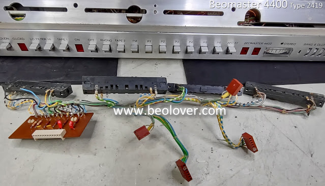
The next disassembly task is to remove the slider controls along with their wire harness.
With them removed it will be easier to clean them.
Looking at the slider controls for this Beomaster 4400 reveals that they are a different type than previous Beomaster 4400 receivers I have worked on. These controls are mounted with a pair of metal clips and some double-sided tape. This Beomaster unit is an earlier model serial number than other units I have seen. The later model units change to a different slider that mounts to the control panel with screws.
Here is a slide control from this Beomaster 4400.


This is going to be a fun task reinstalling this type of control.
Here is the Beomaster 4400 with the controls and harness removed.
Here is the Beomaster 4400 with the controls and harness removed.

On the back side of the Beomaster 4400 I removed the four heatsinks that are for the output amplifier transistors. The heatsinks physically attach to the transistors they protect by screws that also secure the heatsinks to the cabinet frame.
In order to have the main circuit board (PCB 5) free to move when I replace the capacitors I need the heatsinks removed.
Since the heatsinks have to be removed I always redo the thermal coupling of the transistors to the heatsinks. I usually use SIL_Pads for the coupling instead of thermal paste.

Everything I have removed and examined so far on this Beomaster 4400 are things I always do on a restoration of this component.
It is often enough.
However, on this unit I know from playing with the front panel switches that there is some issue with the "Off" switch not resetting the selected source switch.
In order to investigate that I will have to disassemble the rest of the Beomaster 4400 front panel.
I always kind of dread that because it is a big job. It involves desoldering quite a few wires as the Beomaster 4400 wire harness to the front panel involves a lot of hard wired connections instead of connectors. I'm sure that was due to space the connectors would take up.
I always kind of dread that because it is a big job. It involves desoldering quite a few wires as the Beomaster 4400 wire harness to the front panel involves a lot of hard wired connections instead of connectors. I'm sure that was due to space the connectors would take up.
It is a task that must be performed though. Not doing it will result in problems with the Beomaster 4400 operation so that would not be acceptable.
In the next post I will get started with the disassembly of the front panel.
No comments:
Post a Comment
Comments and suggestions are welcome!