Featured Post

Beolover SyncDrive: DC Platter Motor Replacement for Beogram 4002 and 4004 (Type 551x and 552x)

Late Beogram 4002 and the 4004 (Types 551x and 552x), which have DC platter motors instead of the earlier synchronous AC motors usually suff...

Sunday, August 13, 2017

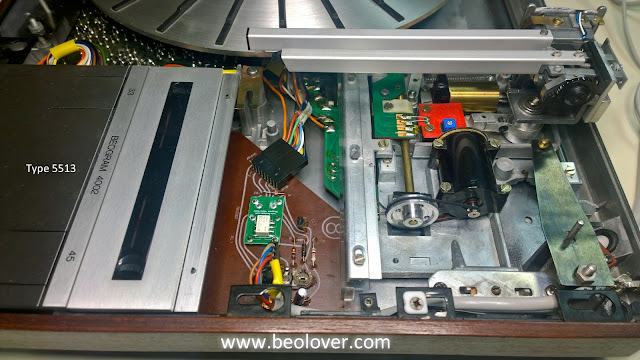
Beogram 4002 Type 5513: Changing out the tonearm phono cartridge connector

This Beogram 4002 project has been on hold since the end of June in order to get a fresh shipment of Beolover replacement parts for the Beogram 400x tonearm cartridge mounts. Now that they are available I snagged one to install in this Beogram.

This Beogram 4002 unit has a defect in one of the cartridge connector contacts. I don't know if the defect came that way from the factory or deteriorated with use. The owner has had some problems with cartridge mounting so we felt it warrants changing out the connector on this one.


It is unusual to replace the cartridge mount in the Beogram 4002. It is the Beogram 4000 that quite often has broken (or near broken) cartridge mounts that require a replacement. In any case we hate to steal a working cartridge mount from another Beogram because that still means a Beogram is left without a working tonearm. So having a replacement part such as the Beolover connector is a wonderful solution.

I begin the procedure on the right side of the Beogram so I can loosen the two mounting screws for the tonearm.


There is a small board in the tonearm that transfers the phono signal from the very thin wire in the tonearm base to the color coded wire that travels down to the cartridge connector. This allows the tonearm to be de-soldered and removed at small board and we can use the color coding to put things back correctly.

I un-solder the red and white wires from the top of the board with the tonearm in its normal position.
Then I flip the tangential arm assembly over to get to the underside of the board for the blue, green and gray wires. The tangential arm assembly rails and drive screw have to be removed to allow this maneuver. It is worth it though as you don't want to make a mistake here.


With the tonearm completely removed I dip the end with the connector into some boiling water for a minute then into ice water. A push on the connector through the back end of the tonearm should break the connector loose so it can be removed.

This one came out on the first attempt. Sometimes it takes more.


If you have to re-use the tonearm wires then take care in this operation. I always like to install new wires that are a little smaller (36 gauge).

Here is the original cartridge connector removed and opened up. It comes in two halves (an upper and lower). This repair keeps the lower half and replaces the upper part of the connector.
As you can see in the pictures, the red highlighted areas show this connector has a broken or worn area of one of the contacts (left channel low signal).


Here is the Beolover replacement part for the upper section of the connector. I tinned the four contacts in preparation for the new phono wires.


I replaced all five original wires in the tonearm with the same color 36 gauge wire except for the ground wire which I changed from gray to black (just a personal preference).


To keep the wires down in the channel before gluing the connector halves together I use some Aleene's Tacky Glue. It is a handy glue that is removable if necessary. I don't want permanent epoxy here.


Once the glue is dry I put the wires right at the connector end into a small bundle so it will be easier to remove this connector again in the future. When I glue the two connector halves back together I use Aleene's glue again for that and I attach a cartridge so I make sure I have the connector pieces aligned properly.


When I re-insert the connector and wires back into the tonearm tube I place a little more Aleene's glue on the sides of the tube (on the inside). That way no glue will get on the end of the connector or the cartridge.


The above photo shows the cartridge removed but when I inserted the connector for real I always have a cartridge attached to insure a proper installation of the connector.

The cutting, stripping, tinning and soldering of wires onto the transfer board takes some patience. I did the red and white wires on the top first again, then flipped the transport over for the remaining three.


The transport is then flipped back over to its proper position and the tonearm is carefully re-attached.
You have to be very gentle tucking the phono wires back into the tube as you re-install the tonearm to the tonearm mounting hardware.


After the tangential arm assembly is put back together I did have to recheck the following alignment adjustments: the stylus tracking path, the tracking force weight and the tangential arm tracking sensor operation.


Back to an audio system for record play testing... both channels play beautifully through the new cartridge connector.


Friday, August 11, 2017

Beogram 4004 Type 5526: Electrical & Mechanical Work Complete...First Play Test

I will begin this post with a picture of the Beogram 4004's first play test. It feels great to listen to some Stevie Ray Vaughan playing while I compose the blog report.

To get to this point from the last post I had to install the two Beolover replacement LED modules for the speed trimmer indicator lamps and run the 24 hour platter speed stability test.

Here are some pictures of the speed indicator LED replacement.


The LED lamp replacements on this speed trimmer circuit reduce the load on the Beogram motor control enough to show up as a final improvement on the 24 hour speed stability test. This of course goes hand in hand with the Beolover restoration of the DC platter motor, new trimmers on the main board and the new RPM speed selection relay.


Here are two plots of the 24 hours speed tests I performed on this Beogram motor. The first one, back in May, was with the Beogram before any restoration. The second plot, from the last 24 hours, shows the dramatic difference in the platter speed test results after the completed mechanical and electrical restoration work.


Monday, August 7, 2017

Beogram 4004 Type 5526: Finalizing Mechanical Adjustments

As usual with these Beogram 400x turntables it takes a good number of iterations on the mechanical adjustments before I am satisfied that the turntable is correctly aligned and ready to play records again.

The remaining final adjustments on this Beogram 4004 were the platter height adjustment, tracking force calibration, stylus tracking path check, stylus set down limit and the tangential tracking sensitivity.

For the height adjustment of 23mm between the Beogram platter deck and the top of the fixed arm I ran into a problem where the tangential arm assembly wasn't level enough with the floating chassis frame.

I stripped the Beogram chassis down again and moved the set screws for tangential arm assembly height so they could be adjusted from the top instead of underneath the floating chassis. This will save time in the future and not require taking everything apart again if that adjustment needs to be tweaked.

I ran into a second problem which was with one of the set screws on this Beogram. Someone previously had damaged one of the set screws where it could not be removed. I had to use a Dremel tool to drill it out, then re-tapped the hole for a replacement set screw from my spare Beogram 4004 unit.


Once I was passed that issue it was pretty straight forward to adjust the tangential arm assembly, using the set screws, to get the fixed arm level with the chassis.


I re-installed the floating chassis in the Beogram case and adjusted the platter so the top of the platter is 23mm from the top of the fixed arm. Sorry for no pictures but here is a link to some reference pictures from a previous project.

With the deck height set I went about calibrating the tracking force for the cartridge. The way I like to do that is to set the tracking force wheel to 1 gram, then adjust the counter weight and tracking force wheel as necessary so I measure 1 gram with my digital cartridge scale.


Since I haven't put the Beogram deck completely back together I needed a good base for the scale to rest on in order to measure the tracking force. The ridges on the Beogram 4004 platter don't allow room to put the scale under the tonearm so I borrowed a platter from a Beogram 8002 turntable which is completely flat.

I also left the Beogram 8002 platter in place for the stylus tracking path check.


For the stylus lowering limit adjustment though I switched the platter back to the Beogram 4004 platter as the adjustment is to make sure the stylus lowering limit clears the first ridge of the platter.


That is to protect the stylus if the Beogram ever fails to detect that a record is not present.

Everything is looking good so far. The final adjustment I make is the tangential tracking sensitivity. With the platter belt disconnected from the platter motor I can manually rotate the platter. The adjustment is to set the tonearm down on a record track, then adjust the tracking detector so the tangential arm drive motor begins rotating after a couple of (manual) platter rotations. After that the tangential arm motor should move the arm a little bit on every rotation. Obviously the exact results of this check can vary some depending on the record you use for the test. The Beogram service manual calls for a specific B&O test record (3621001) and track (5) that I have never been able to find. So I typically use a couple of old records I have and test the tracking sensitivity on several tracks.

Once the tracking is set I test play the old record and watch the tangential tracking system do its work.


Next step is to connect this Beogram to my listening room amplifier for the first record play test.

Saturday, August 5, 2017

Beogram 8000: Tonearm Lowering & Raising Components

In my recent Beogram 8000 project I had to investigate the tonearm lowering and raising functionality. I have also had to look at the part of the Beogram 8000 on one of my own units (where the lowering was sticking, then suddenly dropping). I thought is would be useful to post some details of the Beogram 8000 components involved with the tonearm lowering and raising control.

First are a couple of pictures of the tonearm in the raised position to get familiar with some of the key players.


There is a solenoid involved that is controlled by the Beogram microcomputer and an op-amp circuit that generates a ramp signal to lower and lift the arm via a lever and control bar.

The above pictures show the control bar pressing down on a tonearm linkage component. There is a slot in the exposed end of the linkage to adjust the (vertical) parallelism of the tonearm. Adjusting the linkage position affects the gap between the tonearm and fixed arm.

When the control bar is pressed down on the linkage the tonearm is at its fully raised position. There is a metal spring mechanism that the normal position is designed to keep the arm raised. The solenoid plunger moves a lever that presses against the spring to raise the control bar (and allow the tonearm to lower).

The next picture shows the Beogram with the tonearm in the lowered position.


This picture was taken with the Beogram actually playing a record. You can see the control bar was pushed away (by the solenoid) to allow the tonearm linkage free movement. When the control bar is raising it does so with a controlled motion so the arm slowly lowers to the vinyl record. When the stylus touches the groove the tonearm obviously reaches the limit of its drop. The control bar continues to raise a bit more so it is no longer in contact with the linkage.

At this point the tonearm movement is controlled by the record groove and the Beogram tangential tracking detection.

Here are a couple pictures of the arm lowering/raising components on a stripped down Beogram 8000. The tonearm is removed in these photos. Only the pivoting base remains. These pictures give a good view of the control bar. You can see that the bar travel is managed by a guide slot in a metal bracket.

WARNING: Removal of the tonearm is not part of any adjustment procedure of the Beogram 8000. Attempting to remove the tonearm can cause serious damage and render your Beogram unusable. This is because of the delicate phono wires that travel through the arm and pivot base. These pictures were available for me to make because the Beogram pictured was a damaged unit where the tonearm wires were severed.


Here is a photo from the back of the Beogram with tonearm installed showing another angle of the control bar.


One more photo of the control bar and related components from underneath the tangential arm assembly.


The above photo also shows the location of the adjustment screw for the other tonearm parallelism (horizontal) adjustment. This is for aligning the top surface of the tonearm with the fixed arm when the tonearm is in the raised position.

Now for a look at the electronic part of the arm lowering and raising. Here is the relative circuit as taken from the service manual schematics. The phono cartridge muting circuit is also shown as both the muting and arm lowering/raising are controlled by the same signal from the Beogram microcomputer.


The part of the circuit shown as my test point (TP) for the lowering/lift integrator signal is the drive signal for the solenoid. When the arm is being lowered that signal is a slow ramp signal from 0V up to around 12.6V. When the arm is being raised it is a fast signal from about 12.6V down to 0V.

Here is a view of the arm lowering and raising signals at the test point relative to the microcomputer control signal.


So far in my encounters with these Beogram 8000 turntables, any issues with the tonearm lowering and raising have been mechanical problems. Something interfering with the mechanical movement of the arm lowering/raising components.

If you are having problems with this area I recommend putting the Beogram in service position and studying the movement of the control bar in relation to the arm linkage as well as the movement of the solenoid.

I observed on one of my troubled turntables the solenoid and control bar operating correctly but the arm linkage was sticking, then dropping all at once. I took apart most of the involved components and made sure everything was clean and nothing was interfering with the movement. Once re-assembled the arm lowering worked perfectly again.

If there is a problem where the solenoid isn't working, here are some pictures of the Beogram 8000 solenoid components disassembled. I mention again that I haven't encountered a failed solenoid yet and these pictures were taken from one of my spares just to have as a reference.


I hope the pictures are useful to you Beogram 8000 owners wanting to trouble-shoot any tonearm lowering problems.

Wednesday, August 2, 2017

Beogram 8000: FOD Bites Me In the ***

Having a little experience in the aircraft industry I know about the acronym FOD (Foreign Object Debris). This post is an example of why the term exists and how it can even apply to turntable restoration.

In my recent Beogram 8000 restoration I was extremely happy with the final results and shipped the turntable back to the owner. Although the packing was as good as it could be there was undoubtedly a lot of vibration during the truck journey. When the Beogram 8000 arrived back home the owner noticed the tonearm was drooping. That should never happen. After failed attempts to solve the problem by phone the Beogram had to be shipped back to the workbench.

As soon as it arrived back I unpacked up the Beogram 8000 and saw that the tonearm was still drooping down instead of level with the fixed arm.  I put the Beogram into service position and the tonearm popped back into its normal position. That always happens doesn't it?

The question is what could have been causing the problem?  I started examining every detail of the arm lowering and raising parts. It is natural to suspect the arm control solenoid and some electronic control but this Beogram had extensive bench testing without any such incident. I was pretty sure the problem was mechanical.

Here are some pictures of the Beogram 8000 arm lowering/raising parts.


I exercised the arm lowering and raising manually to see if I could feel any restriction but everything was nice and smooth operating. I also powered up the Beogram and operated the Play/Pause/Stop functions a number of times while observing the solenoid action. No problems there. I wondered if something in the tonearm linkage just slipped a little during shipping and now it is all okay.

One new thing I did notice about this Beogram was that the tangential arm carriage drive was noticeably louder going forward than returning to the parked position. Of course I remembered that this turntable had a broken tangential drive shaft bearing. I had reversed its position and it worked fine while it was here earlier. I didn't discern any difference in the tonearm scanning (noise) at that time. However that damaged plastic lip on the bearing must be the source of why one scan direction is now louder than the other.

So while I hadn't found the source of the tonearm drooping problem I felt I needed to go ahead and fix this tangential drive noise issue. I had one spare drive bearing remaining in my stock so I grabbed it and prepared the install. This operation means taking the tangential drive off its rails and flipping it over to get to the bearing. While there I can also examine the tonearm lowering and raising components from another angle.

This is where I discovered the prime suspect of the tonearm problem. A piece of FOD was visible near the arm control lever.


That piece looks familiar! I looked at the tangential drive bearing and sure enough, that is the piece that had broken off the bearing...probably years ago.


If that small piece of plastic had shifted into the slot that the tonearm lowering bar slides in it could easily have caused the problem where the arm would not fully raise. I can only surmise that is what happened but it seems highly likely. The Beogram hadn't and still doesn't exhibit any bad behavior with the arm functionality. I don't think it is a coincidence that this plastic piece was in the location I found it and it not be the prime suspect.

I installed the new, fully intact, spare drive bearing and the tangential arm scanning operations are smooth again.  They operate with only the expected, soft whirring of the motor.


Now for the important lesson (re)learned about FOD. Seeing that the original bearing had a broken piece off the lip I should have done a more thorough inspection of the Beogram to search for it. I had just assumed it was long gone. On the Beogram 400x turntables where their transport lock bushings are often deteriorated into a thousand pieces I have to do a full cleaning of every part. This incident shows that even one broken piece of plastic debris can cause problems.

I am an optimist though so I take the view that this was a good learning experience and this Beogram needed the drive bearing changed anyway so it worked out good. It is time for a quick play test then I will ship it back home again.