Featured Post

Beolover SyncDrive: DC Platter Motor Replacement for Beogram 4002 and 4004 (Type 551x and 552x)

Late Beogram 4002 and the 4004 (Types 551x and 552x), which have DC platter motors instead of the earlier synchronous AC motors usually suff...

Showing posts with label Beogram 8000. Show all posts

Sunday, October 31, 2021

Beogram 8000: Wrapping up the Workshop Beogram with speed sensor replacement testing

It is time to wrap up testing with the Workshop Beogram 8000 for now.  
The test platform has helped me restore and repair five sets of Beogram 8000 circuit boards along with using the quick connect/disconnect socket on five uC (2IC1) devices.

The Workshop Beogram also gave me a way to test the speed sensor (OPE2).
I discovered that I had two faulty speed sensor devices in my collection of Beogram 8000 parts so this last Workshop Beogram 8000 blog post will show the result of my search for a speed sensor replacement device.

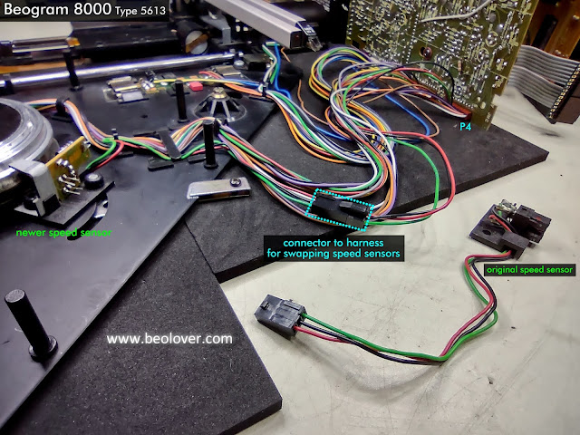
The original two types of speed sensor (OPE2) devices in the Beogram 8000 are these two Bang & Olufsen part numbers - 8330007 (the early type sensor with resistors R46 & R47 on PCB 1) and 8005067 (the later type sensor with resistors R2 & R3 on the speed sensor assembly).
I don't know the story with those part numbers but the 8005067 assembly is what is called out in the later model Beogram 800x turntables (BG8000 & BG8002).  Maybe B&O had reserved that OPE2 part number but didn't release it until later.

Both sensor devices were similar slot type optical switches.  They consist of an emitter that is an IR LED light source and an NPN photo transistor sensor. They are a single assembly with four leads.


Here are the two types of Beogram 8000 speed sensor assemblies.


Here are the wiring diagrams for both speed sensor assembly types.


I was unable to find data sheets for either type of speed sensor that B&O used for these two types of slot type optical sensors.

However, I did find a few good candidates that are the same size and have the same pin configuration (same layout of the leads).

To check these sensors out I have one more bench test mode for my Workshop Beogram 8000.  That is an empty floating chassis with a platter hub/tachometer and the mount for a speed sensor.
Electrically I run the wires from the speed sensor I am testing to a breadboard setup to measure the slot optical sensor output (with an oscilloscope).  The breadboard contains necessary current limiting resistors (R46/R47 or R2/R3).  I use a bench power supply to provide the +15 VDC power for the circuit.

The first tests are for a B&O 8330007 speed sensor device.


Because this is an 8330007 B&O speed sensor I am using current limiting resistors per the schematic. It also matches what was installed on the PCB 1 board for this type of sensor assembly.

Applying the +15 VDC power to this circuit and manually rotating the platter hub here is the oscilloscope measurement.


This 8330007 device is a working speed sensor that I have also functionally tested with the Workshop Beogram 8000 turntable.
The amount of current this sensor circuit draws with the +15 VDC power applied is 30mA.

The second test setup is with a B&O 8005067 speed sensor assembly. It has built in current limiting resistors (R2 and R3).


Since the 8005067 speed sensor assembly has current limiting resistors built into the assembly it isn't necessary to connect up the test components on the bread board like the 8330007 speed sensor.  I can just connect my scope probe and DC power supply directly to the sensor assembly.

With +15 VDC applied to the 8005067 sensor assembly I manually turned the platter hub again and measured the speed sensor signal at the photo transistor collector.  This sensor drew around 20mA while it was operating.


Just like the first sensor, the 8330007, this 8005067 sensor is also a fully working unit that I tested with the Workshop Beogram 8000 turntable.  

In the third test I tried out one of my replacement candidate slot type optical switches.
The device I chose for this test is the TT Electronics/Optek Technology OPB370N55.
Here is the test setup with that device.  It will require the use of the breadboard to provide the current limiting resistors.


To get a usable signal from this new sensor device I had to adjust the trimmers to around 2.4KΩ for R46 and around 6.8KΩ for R47.
Using those values I get a good, healthy speed sensor signal that uses about 10mA with the +15 VDC power applied.  That is half the amount of current used by the 8005067 devices and a third of the amount of current used by the 8330007 devices.


Now that I can see what values I need for the two current limiting resistors I can try out this replacement sensor device in a failed 8005067 speed sensor assembly and test it with the Workbench Beogram 8000 turntable.

Here is my test Beogram 8000 speed sensor with the new slot type optical switch installed.
I am using the 8005067 assembly for the test and I am using 2.2KΩ for R2 and 6.8KΩ for R3.


Before testing the new sensor device under full control of the Beogram 8000 I used my P4 test harness to do a manual check where I rotate the platter hub and measure the sensor signal coming off the sensor and at the microcomputer, 2IC1 pin 40.


That looks perfect.  The raw signal off the OPB370N55 collector is a nice strong signal that feeds the 1IC1 Op-amp before being routed up to the uC pin 40 input (via the signal conditioning flip-flop).

My final check is to connect up the new speed sensor to the Beogram 8000 P4 harness normally and see how it works under full control of the Beogram 8000.

For this test I utilized the Beogram 8000 "Turn" function button.
The signal at the uC pin 40 still looks great and the Beogram 8000 control circuitry has no problem locking in the platter speed.


It looks to me like the TT Electronics/Optek Technology OPB370N55 Slotted Optical Switch is a good replacement for the Beogram 8000 speed sensor device.

If you try it keep in mind that you must change the resistors (either 1R46 & 1R47 or R2 & R3) according to the version your Beogram uses.

There are two other Slotted Optical Switch devices by TT Electronics/Optek Technology that I will try.
OPB871N55 and OPB825.  They will require testing to determine their current limiting resistor values but I believe they could be used as a replacement device as well as the OPB370N55.

This concludes this round of Workshop Beogram 8000 projects.

I will be retooling my workbenches to begin some restoration work on some Beomaster 4400 units next.

Wednesday, October 27, 2021

Beogram 8000: Testing speed sensors with the Workbench Beogram 8000

The Workshop Beogram 8000 unit has already aided me in restoring a number of Beogram 8000 PCB 1 and PCB 2 boards.  One set was extra troublesome as it had some broken traces that were not visible.

This photo shows the boards finally working as I finished off the testing by playing a record.


One thing I discovered in my board testing was that a problem with any part of the speed sensor circuit could potentially cause damage to other components of the platter drive system.  I am referring to the speed sensor itself and the path the signal takes to the Beogram microcomputer (2IC1) pin 40.

Having a problem with the speed sensor is similar to attempting to operate the Beogram 8000 with the rotor removed (sometimes referred to as the sub-platter).  In both cases when the Play or Turn buttons are pressed the Beogram uC will start sending commands to turn the platter.  The uC expects a speed signal as feedback to regulate the platter drive.  When the speed sensor signal is missing (i.e. broken or the rotor is not in place to turn the tachodisc) the uC will keep trying to drive the platter.  Typically what happens is the F1 fuse (300mA, slow for USA model Beogram 8000 turntables) in the transformer compartment will blow and shut things down.  However, damage can also occur to the platter drive transistors 0TR2 and 0TR3.  It would probably also be possible to damage some other components in the platter drive circuitry.

A symptom of a broken sensor signal is that the platter will immediately ramp up to a very high speed when either the Play or Turn button are pressed.  If power is not removed quick enough there can be some component damage.

This problem existed in the PCB 2 assembly of this troublesome set of Beogram boards.
The speed sensor signal was good all the way into the PCB 2 assembly but failed to reach pin 40 of the uC IC due to a broken trace. 

The route of the speed sensor signal to the uC pin 40 can vary depending on when the Beogram 8000 was manufactured or whether it received a service modification.

This photo shows the two types of PCB 2 assemblies found in Beogram 8000 turntables with regard to the speed sensor signal and the uC pin 40.


In the early model Beogram 8000 units the speed sensor signal went from the sensor at the platter hub through an OpAmp (1IC1) then on to 2IC1 (uC) pin 40 via pin 2 of the ribbon cable that connects PCB 1 and PCB 2.

Later in production B&O engineers found that tolerance differences between 1IC1 and 2IC1 could cause periodic variations in the platter speed.  So to solve that problem a 4013 flip-flop circuit was introduced to stabilize the signal.

This makes a difference when trouble-shooting a suspect speed sensor issue.
The early model PCB 2 assemblies had a short trace from the ribbon cable pin 2 over to the 2IC1 (uC) pin 40.
The later models routed the incoming ribbon cable pin 2 over to the new 4013 flip-flop by a yellow wire then returned the conditioned signal to a solder point next to 2IC1 (uC) pin 40 by an orange wire.
So there are more places to lose the signal in the modified PCB 2 assemblies.

In the problem PCB 2 I had to repair, the short trace between the conditioned signal (orange wire) and 2IC1-40 was open. The break was not visible to me but it measured open circuit and the board's primary problem was no speed sensor signal.  Adding a jumper from the conditioned signal directly to 2IC1-40 solved the problem.

I found that it is easy to check 2IC1-40 with an oscilloscope and see if there is a good speed sensor signal. 
However, if the signal is not there then there will not be time to check for the signal and deal with the platter drive having no feedback.

The solution I came up with to make the easy measurement and protect the Beogram circuit components is a new speed sensor test harness for the platter drive cable.
That is the cable that connects to PCB 1 via the P4 board connector.
Disconnecting the P4 cable allows operating the Beogram 8000 without the platter drive in operation.
It is a handy mode when doing things like adjusting the record tracking sensor and setting the tracking force.  

I decided to make a P4 harness that only connected up the three wires for the speed sensor assembly.
This allows me to operate the Beogram 8000 in the mode where the platter drive is disabled except I have the speed sensor signals available to test.

Here is that harness ready to use with my Workshop Beogram 8000.


I have two oscilloscope probes in place.
One for the raw speed sensor signal right at the sensor.  The other will be connected to 2IC1 (uC) pin 40.


Now I can press the Play button or the Turn button and manually rotate the platter hub to check the speed sensor.


Here is a closer look at what the oscilloscope sees at those two measurement points for a properly operating speed sensor.


I now pre-test the speed sensor functionality of a Beogram 8000 using the speed sensor only P4 harness before trying out the full P4 harness.  That way I will get an early warning that there is a problem before risking the loss of a component.

Thursday, October 14, 2021

Beogram 8000: Adding Quick Connect Capability for the Workbench Beogram 8000 uC

Now that I have my Workbench Beogram 8000 up and going I restored and checked out some Beogram circuit boards.

Two Beogram 8000 boards turned out to be real trouble.
Their uC (microcomputer boards - PCB 2) were not functional and they had power supply issues. Perhaps the two problems are related.

In attempting to evaluate the faulty boards I decided to use another Beogram 8000 board to check out the 1IC1 uC devices of the two boards. 

I tried swapping the PCB 2 Microcomputer assembly first but that did not result in a functional Beogram 8000.  

Next I tried swapping just the 1IC1 microcomputer IC.  I also tried two other uC devices.
That did not work either...even when installing the devices in a supposedly working PCB 2 assembly.
I know from working on a lot of these Beogram 800x turntables that the uC devices are pretty durable and it is quite unusual for them to be faulty.  So to have three bad uC devices didn't seem likely.  I needed to do some more testing of those ICs.

Changing the 40-pin uC devices is time consuming. You have to be very careful with them (protect against ESD) and installing them in another 40-pin IC socket is not all that fun.

What I really needed was a (easy) way to install them in my Workbench Beogram 8000.  In my known, working PCB 2 assembly.  The key word being easy.

I decided to modify my Workbench Beogram 8000's PCB 2 to be able to perform quick swapping of 1IC1.

I installed this 40-pin ZIF socket and socket receptacle assembly.


It required a little bit of Dremel surgery on the PCB 2 metal case but I decided that it would be worth it for the ease of swapping uC ICs.

Here is the original 1IC1 uC device re-installed in the new quick connect/disconnect socket.


Does it still work?


Yes...just as good as before.

Now I am ready to check out those suspected faulty 1IC1 devices from the other boards.

The first suspected 1IC1 device is from a board that the owner said the uC was doing strange things.
It would illuminate but sometimes show various combinations of LED segments.
Installing it in my Workbench BG8000 tester the suspect 1IC1 comes up in Standby mode.
That seemed good at first but nothing happens when I pressed the control panel buttons.  The uC appears frozen in that Standby mode.


I believe that confirms the uC IC from that board is indeed bad.

My other two 1IC1 devices however, tested good.
Here is one that I had already jumped the gun and marked as faulty.
Installed in the Workbench BG8000 it performs perfectly.


I feel good about my quick connect/disconnect socket for this Workbench Beogram.
I can see adding a couple of these sockets to one of my Workbench Beomaster 8000 uC boards.

Sunday, October 10, 2021

Beogram 8000: Using the Workbench Beogram 8000 to Test a Speed Sensor Assembly

Now that the Workbench Beogram 8000 test setup has a three-pin connector in the platter drive harness for swapping speed sensor assemblies I can give that a try.

Here is the Workbench Beogram 8000 speed sensor assembly being swapped out with another assembly sent to me for testing.


The speed sensor assembly test candidate was taken out of its P4 wire harness and still has its P4 contacts. The owner should be able to re-insert them when I send back the tested speed sensor assembly.

I ended up making an adapter harness that would plug into my Workbench BG8000 3-pin test connector on one end and has mini-grabber probes on the other end.

In this case the mini-grabbers attach to the wires from the speed sensor assembly being tested.


Exercising the Beogram 8000 Play function with an empty platter I observed the Beogram search for a record while changing from 33.33 RPM to 45 RPM (as expected).  The speeds locked in easily so I think it is fair to say this speed sensor assembly is good.


I was curious as to how this other speed sensor assembly looks compared to the speed sensor that belongs to the Workbench Beogram 8000 turntable.

For that check I re-installed my Workbench BG8000 main board assembly.  That is because it is wired with probes for the sensors. I wanted to use my oscilloscope to capture a picture of the Beogram 8000 speed sensor assemblies at work and see how they compare.

My four probes for this test are -
1. Position Sensor 1
2. Position Sensor 2
3. The speed sensor LDR signal as it comes from the 1P4-7 connector
4. The speed sensor signal as it passes through the 1IC1 op-amp.

Here is a picture of the oscilloscope measurements I made.
I have one image for each sensor assembly at 33.33 RPM and 45 RPM...so a total of four pictures.
I arranged them together on one image so I can align the images to compare the speeds.


Not really surprising, the two sensor measurements do look different (because they are two different light sensitive devices).  However, even thought the signals do look different you can see that the period of the two speed sensor devices is the same (corresponding to 45 RPM and 33.33 RPM).

It is interesting that my Workbench turntable's sensor assembly operates at a 50% duty cycle while the test sensor assembly is less (maybe 35 to 40 percent ?).
That is another measurement I will start making on these Beogram 800x turntable restorations so I can compare them from turntable to turntable.

With both sensor assemblies this Beogarm 8000 was able to lock in the correct platter speed. 
I am declaring this speed sensor assembly sent for evaluation is good.

Saturday, October 9, 2021

Beogram 8000: Adding Speed Sensor Swapping Capability to Workbench Beogram

This is a quick update to show the addition of a new harness connector so the speed sensor assembly on the Workbench Beogram 8000 turntable can easily be changed.

In the previous post I described how the speed sensor assembly changed in Beogram 8000 turntables so for this Workbench Beogram 8000 to be useful in testing components it needs to be able to change the speed sensor assembly according to what type of main board is being connected. More detail on the Beogram 8000 speed sensor change is described by Beolover on this blog post.

There were a couple things standing in the way that prevent easy swapping of the Beogram 8000 speed sensor assembly.

The first problem is the speed sensor assembly is secured in place by two star lock washers. Those are the press to fit metal washers that secure to a mounting post. That type of washer is not meant to be repeatedly removed and refitted. They are designed to be used once. Not very convenient for a workshop test unit where the speed sensor assembly may be swapped out several times.

I decided in this case that since this is a test environment for the Beogram 8000 it was okay to secure the speed sensor assembly to the mounting posts with rubber grommets. They wouldn't be good for a long term installation but in this case they work quite well.


The second problem is the wiring of the sensor assembly from its harness to the main PCB.
The speed sensor is part of the platter drive harness that connects to the P4 connector of PCB 1.
It wouldn't be convenient to require changing out the whole harness just to change the speed sensor assembly.  It would also be a pain to de-solder and re-solder the three wires for the speed sensor each time.

The best thing would be to install a three pin connector just for the speed connector which is what I did.


The wiring for the speed sensor assembly easily connects and disconnect from the harness now.

Caution: Never operate the Beogram 8000 (or 8002) with only the hub attached. The black sub-platter is actually the rotor on these turntables so without it in place the Beogram control circuit will think it needs to keep driving the platter.  That will usually blow a fuse in the transformer. The sub-platter/rotor must be in place if attempting to operate the Beogram. 
Optionally you can disconnect the P4 connector from PCB 1 so all of the platter drive components are not connected.

A quick test to make sure everything still works with the test connector in place shows that the Beogram 8000 control circuit can still regulate the platter speed perfectly.


This modification to the Workbench Beogram 8000 allows me to easily configure the speed sensor according to the type of PCB 1 I am testing but what if I am trying to test out a different speed sensor assembly?

For that case I need to make a little adapter harness that allows for a speed sensor assembly test subject to connect its three wires (that I will assume will be loose) to a connector that will mate with my platter motor harness.

I think I will make the end of the adapter for the loose wires be one of those screw to tighten type of connectors.

That will have to be in the next post.

Friday, October 8, 2021

Beogram 8000: Utilizing the Workshop Beogram 8000 to Test a Board

It is time to put the Workshop Beogram 8000 to work.

I received some Beogram 8000 main boards (with their microcomputer boards attached) for testing and this post will show an easy use of the Workshop Beogram 8000. 

That is to do a restoration on the main circuit board and the microcomputer board then check that it works.
Since my Workbench Beogram 8000 is fully tested and working, swapping out the main PCB should result in the Beogram still fully functional...if the restoration is all good :-).

First though...A bit of caution regarding board swapping on a Beogram 8000.
Anyone that has worked on a Beogram 8000 will have noticed that there seems to be a lot of modification work on the electronics of these units. As a comparison, the Beogram 8002 electronics typically have no modifications.  My guess is that with the Beogram 8000 being a totally new design (especially technology-wise) from the previous Beogram 4002/4004 tangential arm turntables there were a lot of post-production hiccups that had to be addressed with service bulletins and mod kits.
One such modification was when B&O changed the speed sensor assembly in the Beogram 8000.
Beolover has a really good explanation of this issue as he ran into it in this 2020 blog post.

The important thing to take away from that is DO NOT put a Beogram 8000 main board that has the circuit modification for the newer speed sensor into a Beogram 8000 that is using the older type speed sensor assembly.  The reason being is that the newer circuit board is expecting the resistor between +15V and the speed sensor light source to be on the speed sensor assembly.  The older speed sensor assemblies DO NOT have a resistor there. They expect the resistor (R46) to be on the main board.
The result will be damaging (blowing) the speed sensor light source if this pairing is done.

Here is a photo of the two types of speed sensors.


You can see in the photo that the newer speed sensor has the addition of a small board with two resistors moved from the main PCB.

These next two photos show a board configured for the original speed sensor assembly and one configured for the new speed sensor assembly.


In my case of restoring this first board that was sent to me I don't have to be concerned about a conflict with the speed sensor assembly as my Workbench Beogram 8000 currently is fitted with the newer type speed sensor and the board sent for restoration is designed for the newer type speed sensor. 

Here is the current speed sensor assembly on the Workbench Beogram 8000.


To make the Workbench Beogram 8000 capable of testing both configurations of the main boards I will need to make a modification of my own to this test setup so I can quickly and easily change speed sensors. 

But first I will finish this first Beogram 8000 board set.

Here are the "before" photos.

The electrolytic capacitors will all be replaced. Board connector mounting points will all be re-soldered.


In the case of the small microcomputer board I removed the microcomputer IC so I have more room to work on the C28 capacitor and also to upgrade the 40-pin IC socket for the microcomputer IC.


Here is the board ready to begin work on.
As usual I pulled the mounting base off the large 2200uF capacitor so I can re-use it on the replacement capacitor.


I like to start with the microcomputer board assembly and get that part out of the way.
Here is the microcomputer IC back in place (in its new socket) and the new C28 capacitor.


The rest is just selecting and fitting capacitors and soldering.
Here is the board set completed and ready to install in the Workbench Beogram 8000.


Hooking up the transformer, connectors, control panel then plugging the Beogram in brings up the reassuring Standby dot LED that things are going good.


I pressed the Play button with the platter empty and observed the Beogram search for a record and automatically switch platter speeds.  Not finding a record, it returned home and stopped.


After that initial test I verified the power supply voltages on the board. They were all good.
As a final check I put on a record and checked out the record play handling.
Initial set down and drive through the lead-in groove was perfect.
So was the run-out groove and end-stop detection.
I also tested the Pause memory function and it worked correctly.
That is where you press Pause while playing a record. Leaving the Beogram with a record on the platter in the Pause mode for a few seconds will cause the Beogram microcomputer to think you stepped away for a bit. The Beogram will return the tonearm assembly to home and go into Standby mode.
When you press Play again the Beogram will return the tonearm to the spot you paused the previous play and resume from there.  Quite a nice feature.

I believe this board set is complete and ready to send back to its owner.

The next set is one with the circuit for the original type speed sensor assembly so I will need to change that sensor assembly for that project.