This is a quick update to show the addition of a new harness connector so the speed sensor assembly on the Workbench Beogram 8000 turntable can easily be changed.
In the previous post I described how the speed sensor assembly changed in Beogram 8000 turntables so for this Workbench Beogram 8000 to be useful in testing components it needs to be able to change the speed sensor assembly according to what type of main board is being connected. More detail on the Beogram 8000 speed sensor change is described by Beolover on this blog post.
There were a couple things standing in the way that prevent easy swapping of the Beogram 8000 speed sensor assembly.
The first problem is the speed sensor assembly is secured in place by two star lock washers. Those are the press to fit metal washers that secure to a mounting post. That type of washer is not meant to be repeatedly removed and refitted. They are designed to be used once. Not very convenient for a workshop test unit where the speed sensor assembly may be swapped out several times.
I decided in this case that since this is a test environment for the Beogram 8000 it was okay to secure the speed sensor assembly to the mounting posts with rubber grommets. They wouldn't be good for a long term installation but in this case they work quite well.

The second problem is the wiring of the sensor assembly from its harness to the main PCB.
The speed sensor is part of the platter drive harness that connects to the P4 connector of PCB 1.
It wouldn't be convenient to require changing out the whole harness just to change the speed sensor assembly. It would also be a pain to de-solder and re-solder the three wires for the speed sensor each time.
The best thing would be to install a three pin connector just for the speed connector which is what I did.
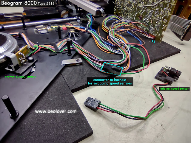

The wiring for the speed sensor assembly easily connects and disconnect from the harness now.
A quick test to make sure everything still works with the test connector in place shows that the Beogram 8000 control circuit can still regulate the platter speed perfectly.


For that case I need to make a little adapter harness that allows for a speed sensor assembly test subject to connect its three wires (that I will assume will be loose) to a connector that will mate with my platter motor harness.
I think I will make the end of the adapter for the loose wires be one of those screw to tighten type of connectors.
That will have to be in the next post.
No comments:
Post a Comment
Comments and suggestions are welcome!