Featured Post

Beolover SyncDrive: DC Platter Motor Replacement for Beogram 4002 and 4004 (Type 551x and 552x)

Late Beogram 4002 and the 4004 (Types 551x and 552x), which have DC platter motors instead of the earlier synchronous AC motors usually suff...

Showing posts with label speed sensor assembly. Show all posts

Sunday, October 10, 2021

Beogram 8000: Using the Workbench Beogram 8000 to Test a Speed Sensor Assembly

Now that the Workbench Beogram 8000 test setup has a three-pin connector in the platter drive harness for swapping speed sensor assemblies I can give that a try.

Here is the Workbench Beogram 8000 speed sensor assembly being swapped out with another assembly sent to me for testing.


The speed sensor assembly test candidate was taken out of its P4 wire harness and still has its P4 contacts. The owner should be able to re-insert them when I send back the tested speed sensor assembly.

I ended up making an adapter harness that would plug into my Workbench BG8000 3-pin test connector on one end and has mini-grabber probes on the other end.

In this case the mini-grabbers attach to the wires from the speed sensor assembly being tested.


Exercising the Beogram 8000 Play function with an empty platter I observed the Beogram search for a record while changing from 33.33 RPM to 45 RPM (as expected).  The speeds locked in easily so I think it is fair to say this speed sensor assembly is good.


I was curious as to how this other speed sensor assembly looks compared to the speed sensor that belongs to the Workbench Beogram 8000 turntable.

For that check I re-installed my Workbench BG8000 main board assembly.  That is because it is wired with probes for the sensors. I wanted to use my oscilloscope to capture a picture of the Beogram 8000 speed sensor assemblies at work and see how they compare.

My four probes for this test are -
1. Position Sensor 1
2. Position Sensor 2
3. The speed sensor LDR signal as it comes from the 1P4-7 connector
4. The speed sensor signal as it passes through the 1IC1 op-amp.

Here is a picture of the oscilloscope measurements I made.
I have one image for each sensor assembly at 33.33 RPM and 45 RPM...so a total of four pictures.
I arranged them together on one image so I can align the images to compare the speeds.


Not really surprising, the two sensor measurements do look different (because they are two different light sensitive devices).  However, even thought the signals do look different you can see that the period of the two speed sensor devices is the same (corresponding to 45 RPM and 33.33 RPM).

It is interesting that my Workbench turntable's sensor assembly operates at a 50% duty cycle while the test sensor assembly is less (maybe 35 to 40 percent ?).
That is another measurement I will start making on these Beogram 800x turntable restorations so I can compare them from turntable to turntable.

With both sensor assemblies this Beogarm 8000 was able to lock in the correct platter speed. 
I am declaring this speed sensor assembly sent for evaluation is good.

Saturday, October 9, 2021

Beogram 8000: Adding Speed Sensor Swapping Capability to Workbench Beogram

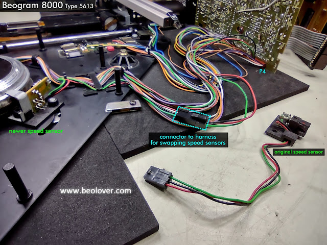
This is a quick update to show the addition of a new harness connector so the speed sensor assembly on the Workbench Beogram 8000 turntable can easily be changed.

In the previous post I described how the speed sensor assembly changed in Beogram 8000 turntables so for this Workbench Beogram 8000 to be useful in testing components it needs to be able to change the speed sensor assembly according to what type of main board is being connected. More detail on the Beogram 8000 speed sensor change is described by Beolover on this blog post.

There were a couple things standing in the way that prevent easy swapping of the Beogram 8000 speed sensor assembly.

The first problem is the speed sensor assembly is secured in place by two star lock washers. Those are the press to fit metal washers that secure to a mounting post. That type of washer is not meant to be repeatedly removed and refitted. They are designed to be used once. Not very convenient for a workshop test unit where the speed sensor assembly may be swapped out several times.

I decided in this case that since this is a test environment for the Beogram 8000 it was okay to secure the speed sensor assembly to the mounting posts with rubber grommets. They wouldn't be good for a long term installation but in this case they work quite well.


The second problem is the wiring of the sensor assembly from its harness to the main PCB.
The speed sensor is part of the platter drive harness that connects to the P4 connector of PCB 1.
It wouldn't be convenient to require changing out the whole harness just to change the speed sensor assembly.  It would also be a pain to de-solder and re-solder the three wires for the speed sensor each time.

The best thing would be to install a three pin connector just for the speed connector which is what I did.


The wiring for the speed sensor assembly easily connects and disconnect from the harness now.

Caution: Never operate the Beogram 8000 (or 8002) with only the hub attached. The black sub-platter is actually the rotor on these turntables so without it in place the Beogram control circuit will think it needs to keep driving the platter.  That will usually blow a fuse in the transformer. The sub-platter/rotor must be in place if attempting to operate the Beogram. 
Optionally you can disconnect the P4 connector from PCB 1 so all of the platter drive components are not connected.

A quick test to make sure everything still works with the test connector in place shows that the Beogram 8000 control circuit can still regulate the platter speed perfectly.


This modification to the Workbench Beogram 8000 allows me to easily configure the speed sensor according to the type of PCB 1 I am testing but what if I am trying to test out a different speed sensor assembly?

For that case I need to make a little adapter harness that allows for a speed sensor assembly test subject to connect its three wires (that I will assume will be loose) to a connector that will mate with my platter motor harness.

I think I will make the end of the adapter for the loose wires be one of those screw to tighten type of connectors.

That will have to be in the next post.