Featured Post

Beolover SyncDrive: DC Platter Motor Replacement for Beogram 4002 and 4004 (Type 551x and 552x)

Late Beogram 4002 and the 4004 (Types 551x and 552x), which have DC platter motors instead of the earlier synchronous AC motors usually suff...

Showing posts with label broken. Show all posts

Thursday, January 16, 2025

Beogram 4000: Microsurgery on the Tonearm Wiring

In recent days I made nice progress with the Beogram 4000 from Australia that I have on the bench right now. When I thought I was mostly done I wanted to give it a quick spin to see if any sound would come out of the unit. Unfortunately, I quickly noticed that only one of the channels would produce sound. The other was completely dead.

First I did some measurements between DIN5 pins and cartridge mount connection pads (after preventing the grounding switches from closing with a strip of paper). This yielded that indeed the red (right) channel did not seem to be connected. But I also noticed that blue/green (the signal return wiring) seemed to connect to the center tabs and not the outer ones on the cartridge mount, as would be normal. This suggested that some major 'human creativity' had occurred at some point in the past that changed the tonearm wiring fundamentally. Probably in an attempt to fix this issue.

I did a visual inspection of the wiring, and soon found the root cause for the absent continuity of the right channel: One of the very fine wires that go though the bearing of the tonearm assembly was broken off:

If you look very closely you can actually see the other end of the wire peeking though the thin plastic tube a couple mm from the end of the tube. This meant I needed to find a way to restore the wiring. Luckily, this very thin wiring stretch terminates at the bottom end of the bearing where the wires connect to more solid wires across a small PCB acting as a wire terminal:

I decided to try reconnecting the two wire ends. For this to happen I needed to get the ripped off end inside the tube out in the open, so I could solder the two ends back together. I unsoldered the wires from the terminal PCB and then liberated the plastic tube from the clamp that secures it to the bottom of the carriage assembly:
It turned out that the wires sit fairly loosely inside this tube and I was able to push the broken off wire a bit further into the tube, which happily caused the broken off end to emerge. With fine tweezers I pulled the strand a bit further into the open. These wires are so called 'magnet wire', which means they are insulated by a thin coat of polyurethane. This coat can be burned off in a drop of hot solder at the end of the solder iron tip. A puff of smoke and one has uninsulated wire that can then be soldered. I did this to both ends and then tacked them back together after applying a little bit of flux: 
I then insulated the naked wire stretch with some glue:
I verified that this wire was continuous again and then proceeded identifying which of the wires was connected to what wiring color on the MMC mount. This shows how the colors are connected to the Beolover MMC cartridge mounting tab that I had already installed in this Beogram:
One by one I measured where the thin wires were connected at the tab and then I soldered them to the proper terminal to match the colored wiring on the other side:
This shows the final result on the other end. I had pulled the plastic tube out a bit further than before to give the wires some clearance to the metal bearing shaft, hoping to prevent future damage to them due to reduced stress and no mechanical contact:
I installed the carriage back on its rails and then tried listening to a record again. Happily, the music now came from both speakers, so we can conclude that this issue is fixed. Stay tuned for more details about this restoration effort!


Thursday, December 1, 2022

Beogram 4002 (5503): Restoration of the Carriage Position Sensor - Development of a New Beolover Part

The Beogram 4002 (5503) that I am currently restoring had a damaged carriage position sensor photo resistor housing, which had broken off mounting tabs:

I removed the photo resistor housing:
This shows it from the back:
After pulling out the bottom part, the photo resistor can be extracted:
I designed a replacement housing that I can print on a 3D printer. It consists of two parts. This shows them together with the extracted photo resistor:
This shows how to integrate the photo sensor with the assembly:
First straighten the leads of the photo sensor and put it on the insert part like this:
Then slide the main housing over the insert with the photo resistor:
This shows the assembled sensor from the bottom:
Now the assembly can be inserted into the original mounting cutouts:
Once the sensor has been clicked into the PCB, the leads can be soldered to the pads:
I decided to also replace the position sensor light bulb with an LED. This shows the original lightbulb lit up in its housing:
Removal of the housing reveals the light bulb soldered to its two pads:
The right pad is the 24V rail, while the left pad connects to GND via 1R91. It is easy to replace the bulb with a LED: Basically any LED will do. I selected an amber LED with a 2.1cd light output at 20mA that I had in my stash. Since it runs from 24V in this setup, a resistor needs to be put in series to limit the current. I selected a 3.3kOhm resistor that limits the current to about 7mA. This current lights the LED up in a low key way, similar to the output of the light bulb:
This shows the entire restored carriage PCB (I also replaced the 47u electrolytic capacitor and the 8.2 Ohm solenoid resistor):
After I installed the carriage again I tested the sensor output by measuring the collector voltage at TR23, which should give clean 24V signals every time a black segment of the 'plexiglass ruler' gets pulled between the LED and the photo resistor. This shows the signal that the 45 RPM pattern caused, while the carriage swept the platter:
This looks like it should, i.e. we can conclude that the restoration of the carriage position sensor was successful.


Saturday, May 21, 2022

Beogram 4000: MMC Cartridge Mount Restoration

I recently received the tonearm of a Beogram 4000 located in Western Australia. Like in many Beogram 4000s the MMC cartridge mount had broken off.

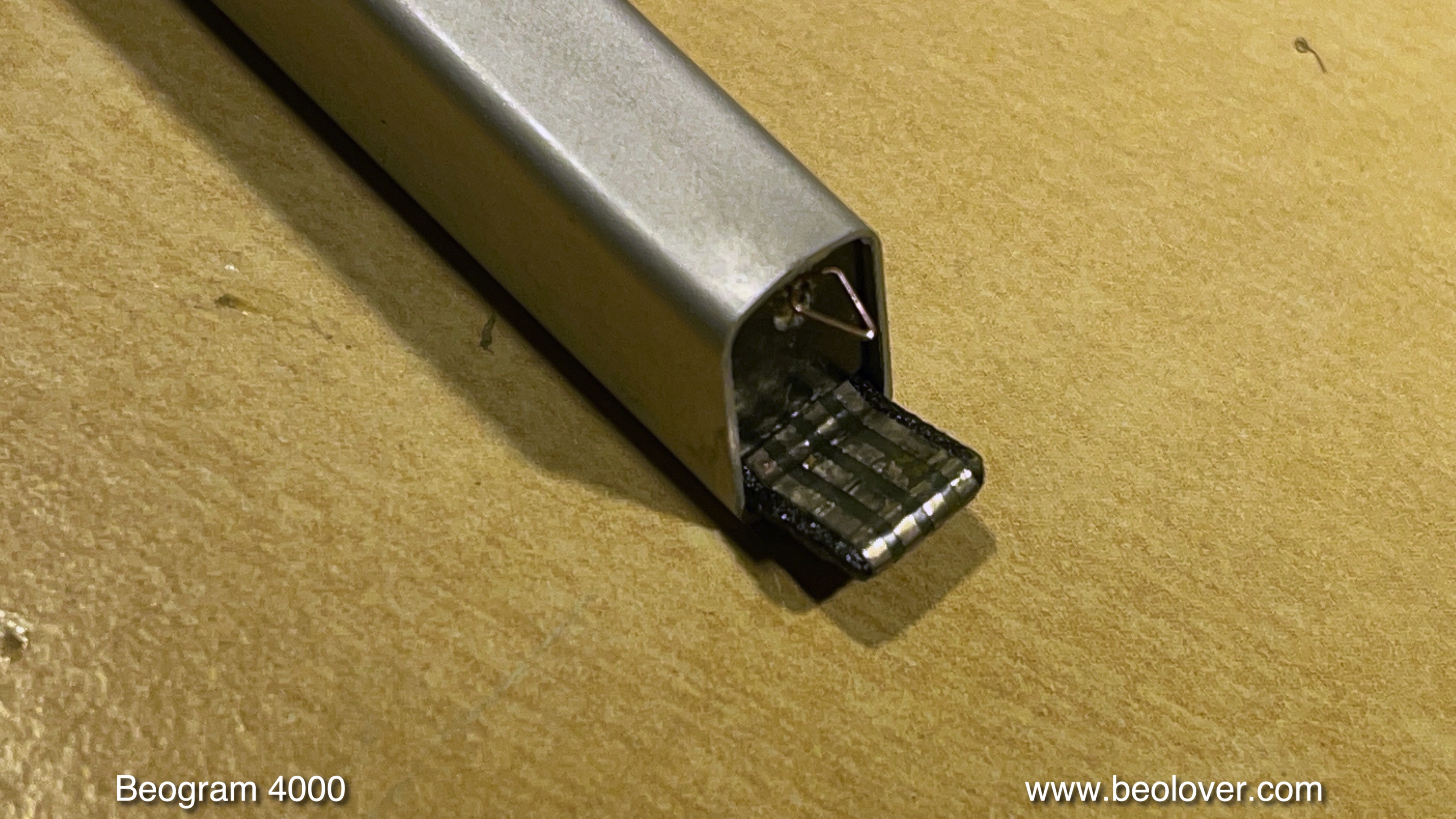
This Beogram still had the 'old style' tonearm, that elegantly plugs into the base of the arm, instead of featuring soldered signal wiring. However, this makes it more difficult to replace the MMC mount since the insert that goes into the aluminum profile tube has an adapter at the rear that has spring loaded contacts that 'grab' the circuit board that reaches into the back end of the arm to make contact. This shows the sad condition of the MMC mount as received:

The first step of any MMC mount replacement is removal of the broken one. They are usually glued into the arms. Luckily, the glue softens when the arms are 'cooked' for 30 min or so. I heated this one together with the also broken one from a Beogram 4000 from the UK that I am restoring right now:

Replacement of the MMC mount is part of my standard Beogram 4000 restoration package since all mounts seem to be quite brittle at this point in time, and it is an unpleasant event if the broken off tab sticks deep in a cherished $800 rebuilt MMC20CL...This shows the liberated insert after the cooking process:
This is the 3D printed replacement part with installed flex-PCB based contact traces:
The back part with the plug-in contacts mounts onto the thin tab at the end of the part:
This shows the signal wires soldered to the new mount:
And this picture shows all the component put back together. I was able to re-use the bottom part of the mount with the grounding contact for the cartridge housing:
After checking all leads for continuity (sometimes these thin wires can be broken inside the insulation) the next step was inserting the assembly into the arm tube:
I put a bit of white wood glue on the sides of the insert when I push it in to make sure it stays put when cartridges are mounted/pulled off. The defunct cartridge makes sure that the front end components of the assembly are positioned correctly to receive cartridges without any gap between housing and arm tube:
And this shows the final result of the operation:
This tonearm is ready to travel back to Western Australia!


Monday, May 2, 2022

Beogram 4000/2/4: Update of Sensor Arm LED Assembly. No More Crumbly Flex-PCB Mess!

I recently re-designed the sensor arm LED assembly for Beogram 4000, 4002, and 4004. The previous version using a flex-PCB proved too difficult to install for some customers. My updated design is based on a small 'hard' PCB that fits precisely into the bulb compartment and uses an insert for proper positioning (it is important that the LED is approximately in the spot the lightbulb filament occupied).

This shows the new components:

And here a still from the video below that shows the LED 'in action':

The LED board produces a nice focused spot on the platter and also the B&O logo is lit up properly in the correct hue.
I updated my original sensor arm video and it shows now how to install these parts in Beogram 4002 and 4004. The video also shows how to update the record detection circuit. It usually benefits from installing a new transistor for amplifying the sensor signal. The procedure for Beogram 4000 is similar, but naturally the board looks a bit different, i.e. you will need to find the transistor for the sensor signal amplification via the service manual. Enjoy!:


Tuesday, January 25, 2022

Beogram 4002/4004: Updated LED Assemblies for Replacing Incandescent Bulbs in the RPM Adjustment Panel

I recently re-designed the circuit boards of the LED assemblies for replacing the regular incandescent light bulbs in the RPM adjustment panels of Beogram 4002 and 4004. The main reason for the re-design was a manufacturer inconsistency in the red-green LEDs that I used in the previous version. This required occasional adjustment of the resistor values to maintain the 'incandescent looks' of these panels. At the same time warm-white LEDs have become much more ubiquitous in recent years, and so I decided to re-design the boards using such warm white LEDs. This shows the new assemblies:


I recorded a video that shows how to install them. Enjoy!:


Friday, September 25, 2020

Beogram 4002 (5503): Unit Switches Immediately to 45 RPM After Pressing Start

The Beogram 4002 (5503) that I am currently restoring exhibited a strange phenomenon when I tested it the first time after rebuilding all its functional parts (more about this process in a subsequent post):

After pressing START the carriage began to move while it immediately switched to 45 RPM. Pressing the 33 key switched it back to 33 RPM, but only as long as the key was pressed.

This immediately suggested that either TR3 or TR2 had an issue. Let's have a look at the relevant section of the circuit diagram:


This is how the speed selection works:
The base of TR3 is connected to the collector of TR4, and the base of TR4 is connected to the collector of TR3. Resistors 5R1 and 5R2 act as pull-up resistors together with the light bulbs IL1/2. I guess the resistors were added to keep the deck working even if a bulb burned out.
This causes a flip-flop behavior: When the base of TR3 is shorted to ground via the 45 switch in the keypad or TR2 (that is activated by the carriage as it travels towards the set-down point for singles), TR3 is turned off for a moment, causing its collector to go high, which in turn pulls the base of TR4 up, and that drives the collector of TR4 to GND since TR4 turns on. This then keeps the base of TR3 permanently grounded and the deck is running at 45 RPM (via switching TR6 on which changes the oscillation frequency of the Wien Oscillator to drive the AC motor at a higher RPM).
The opposite happens when the 33 key is pressed. This causes TR4 to be off and TR3 on, and so TR5 is turned on running the oscillator at a lower frequency.

I removed TR3 and checked it with my transistor tester:

Apparently it had turned into a voltage divider!...;-).
I replaced TR3 with a generic BC547B and that fixed the issue.

Monday, September 21, 2020

Beogram 4000: Replacement of Broken Off MMC Cartridge Mount with 3D Printed Replacement Assembly

I recently received the tonearm of a Beogram 4000 from Belgium. It had a broken off MMC cartridge mounting tab. Sadly, this happens to many Beogram 4000s since they used a plastic that seems to go brittle over the years. Luckily this Beogram 4000 has the old-style MMC adapter insert that connects via spring terminals to a narrow circuit board that sticks in to the arm from the back. This allows easy removal of the arm by just removing one screw and pulling it out. This shows the arm as received:


The plastic tab that inserts into the MMC cartridges is missing and only the flex PCB with the contact traces remained:

It turned out that the plastic insert was glued into this particular arm. This meant I had to simmer this arm for an hour in boiling water in order to soften the glue. After I removed the arm from the hot water I was able to push the assembly out from the back with a rod that fits snugly into the arm. This shows the extracted part:
Luckily, the lower part of the MMC mount with the grounding tab was still intact and could be reused:
The next step was to assemble the replacement part. The first step was to glue the new nickel and gold plated contact traces into the 3D printed plastic part replacement, and transfer the wires over:

Then I assembled the insert. I used a damaged cartridge for positioning the lower part with the grounding tab that it was flush with the installed cartridge. Then I glued the back part with the spring contact tabs onto the 3D printed part:
This shows the back contact tabs after assembly:

The next step was to insert this assembly into the arm in a way that the mounting screw would go straight into the back part while ensuring that the cartridge was snug with the aluminum tube. This was the result:
This is how the MMC mount looks like without cartridge:

Pretty close to the original! This arm is ready for duty again!