Featured Post

Beolover SyncDrive: DC Platter Motor Replacement for Beogram 4002 and 4004 (Type 551x and 552x)

Late Beogram 4002 and the 4004 (Types 551x and 552x), which have DC platter motors instead of the earlier synchronous AC motors usually suff...

Showing posts with label mount. Show all posts

Saturday, May 21, 2022

Beogram 4000: MMC Cartridge Mount Restoration

I recently received the tonearm of a Beogram 4000 located in Western Australia. Like in many Beogram 4000s the MMC cartridge mount had broken off.

This Beogram still had the 'old style' tonearm, that elegantly plugs into the base of the arm, instead of featuring soldered signal wiring. However, this makes it more difficult to replace the MMC mount since the insert that goes into the aluminum profile tube has an adapter at the rear that has spring loaded contacts that 'grab' the circuit board that reaches into the back end of the arm to make contact. This shows the sad condition of the MMC mount as received:

The first step of any MMC mount replacement is removal of the broken one. They are usually glued into the arms. Luckily, the glue softens when the arms are 'cooked' for 30 min or so. I heated this one together with the also broken one from a Beogram 4000 from the UK that I am restoring right now:

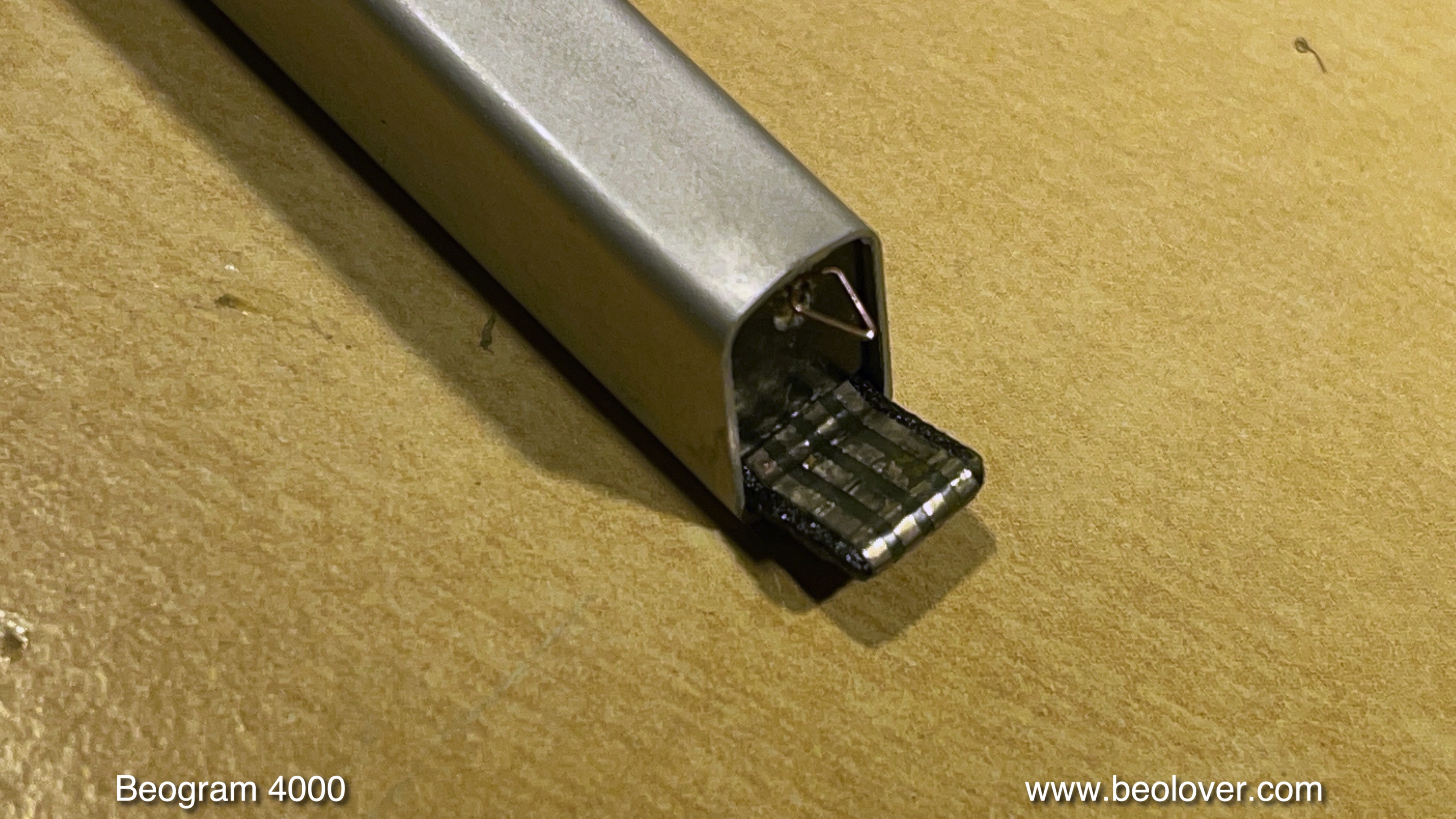
Replacement of the MMC mount is part of my standard Beogram 4000 restoration package since all mounts seem to be quite brittle at this point in time, and it is an unpleasant event if the broken off tab sticks deep in a cherished $800 rebuilt MMC20CL...This shows the liberated insert after the cooking process:
This is the 3D printed replacement part with installed flex-PCB based contact traces:
The back part with the plug-in contacts mounts onto the thin tab at the end of the part:
This shows the signal wires soldered to the new mount:
And this picture shows all the component put back together. I was able to re-use the bottom part of the mount with the grounding contact for the cartridge housing:
After checking all leads for continuity (sometimes these thin wires can be broken inside the insulation) the next step was inserting the assembly into the arm tube:
I put a bit of white wood glue on the sides of the insert when I push it in to make sure it stays put when cartridges are mounted/pulled off. The defunct cartridge makes sure that the front end components of the assembly are positioned correctly to receive cartridges without any gap between housing and arm tube:
And this shows the final result of the operation:
This tonearm is ready to travel back to Western Australia!


Monday, September 21, 2020

Beogram 4000: Replacement of Broken Off MMC Cartridge Mount with 3D Printed Replacement Assembly

I recently received the tonearm of a Beogram 4000 from Belgium. It had a broken off MMC cartridge mounting tab. Sadly, this happens to many Beogram 4000s since they used a plastic that seems to go brittle over the years. Luckily this Beogram 4000 has the old-style MMC adapter insert that connects via spring terminals to a narrow circuit board that sticks in to the arm from the back. This allows easy removal of the arm by just removing one screw and pulling it out. This shows the arm as received:


The plastic tab that inserts into the MMC cartridges is missing and only the flex PCB with the contact traces remained:

It turned out that the plastic insert was glued into this particular arm. This meant I had to simmer this arm for an hour in boiling water in order to soften the glue. After I removed the arm from the hot water I was able to push the assembly out from the back with a rod that fits snugly into the arm. This shows the extracted part:
Luckily, the lower part of the MMC mount with the grounding tab was still intact and could be reused:
The next step was to assemble the replacement part. The first step was to glue the new nickel and gold plated contact traces into the 3D printed plastic part replacement, and transfer the wires over:

Then I assembled the insert. I used a damaged cartridge for positioning the lower part with the grounding tab that it was flush with the installed cartridge. Then I glued the back part with the spring contact tabs onto the 3D printed part:
This shows the back contact tabs after assembly:

The next step was to insert this assembly into the arm in a way that the mounting screw would go straight into the back part while ensuring that the cartridge was snug with the aluminum tube. This was the result:
This is how the MMC mount looks like without cartridge:

Pretty close to the original! This arm is ready for duty again!


Monday, August 10, 2020

Beogram 4000: Replacement of an 'Old Style' MMC Cartridge Mount with a New 3D Printed Assembly

The Beogram 4000 that I am currently restoring also had a cracked MMC cartridge mount. Unfortunately, this is a problem common in many Beogram 4000 since the plastic B&O used for the cartridge mount seems to get brittle as it ages. Later Beogram 4002 and 4004 have cartridge mounts made from a different plastic, and it rarely happens that they break.

The first step was to remove the tone arm to be able to push the plastic assembly out of the arm from the back. Later 4000s have a mount that is glued in and one can remove it by 'cooking' the arm for a while in boiling water to soften the glue until one can push the mount out. More details about this procedure is posted in this blog post.

This post is about doing this replacement for an 'old style' arm, where the mount assembly is bolted into the aluminum profile of the arm. This shows the back end of the arms. The tone arm up front can be removed by taking out the screw that holds the aluminum profile to the arm base:

Then the arm can be pulled out:
Do this carefully, since there is a little spring on the excenter that allows adjusting the arm forward and backward (there is a small plate on it, that has already been removed in the above picture, but is shown in the 2nd picture below under the arm). 
Once the arm is off a small PCB is revealed that makes contact to the MMC mount assembly in the front end of the arm:
Turn the arm around, and the screw that holds the cartridge mount assembly in place can be accessed:
I removed the screw, and then carefully pushed the plastic assembly out from the back of the arm using a 8 mm diameter rod with a smooth end (to not damage the back end of the assembly) that fit into the aluminum profile. The extracted parts are shown in the upper part of the picture below:
The assembly consists of three components: (1) A 'carrier' that also has the tab (broken off) onto which the cartridge is stuck. The tab end of the carrier carries the flex circuit board that has the four traces for making contact to the coils of the cartridge (it came off due to the broken of tab). (2) A separate part that carries a grounding tab to make contact to the metal body of the cartridge, and (3) a part in the back that makes the connection to the PCB reaching into the back of the arm.
Below the extracted parts, the new plastic parts that I designed for this repair are shown. They were printed at Shapeways in black PA12 plastic, which is a sturdy engineering plastic that has a bit of flexibility while also being pretty stiff. Perfect for a cartridge mounting tab that is not supposed to break off when it is torqued a bit.

Since in this case also the grounding tab was damaged, 
I needed to design a replacement for this component, too.
The challenge was to find a suitable metal strip for fashioning a suitable grounding tab. After a bit of head scratching I had the idea to use an 'ammo pack' strip from Molex-style connector terminals:
I removed the terminals and plated the ammo strip with nickel and then with gold. Then I cut a small part off and bolted it into the 3D printed plastic part and bent the end into a suitable tab shape:
The next step was to glue a new flex PCB strip with the coil contacts (also Ni/Au plated) into the business end of the carrier part:
Then it was time to transfer the wiring:
After the soldering was done (use a small tip and be quick not to damage the plastic parts), the insert could be assembled together with the original back end part:
For assembling the ground tab part with the carrier, it is a good idea to stick a cartridge on it, which allows aligning the ground tab part with the back plate of the cartridge. I fixed the ground tab part in place with a dab of super glue gel on either side. The back end was glued on with contact cement (like in the original assembly).
And now came the interesting moment! Would this new assembly line up with screw hole in the arm tube when inserted into the tube?
Luckily it did:
While the cartridge sat snug on the end of the aluminum profile without a gap:
Perfect! This spared me another design iteration to make things match. It rarely happens that a part like this really fits on first attempt, but this time I was lucky! This shows the new cartridge mount with removed cartridge:
Beolovely! 

Time to put the arm back into its place:
A few more adjustments and it will be time to give this Beogram 4000 a first spin!


Sunday, December 10, 2017

Beogram 4000: Replacement of a Cracked Cartridge Mount with a 3D Printed Assembly

Like so many Beogram 4000s, the one I am working on right now had a cracked MMC cartridge mount. In the 4000 this part was made from a more brittle plastic than in the later 4002s, and it seems this material is not aging well. This is how this issue manifests itself:
The first step of this repair procedure is to take the arm out that the original part can be extracted. For this the screw in the back needs to be removed, and then the arm can be pulled out:
after pulling it forward a bit the part that holds the excenter down can be removed, revealing the excenter and the spring that pushes it down:
Pulling the arm further releases a spring that holds the wiring in place:
The the arm comes off and one can see the board where the wires to the cartridge mount are soldered on:
The next step was to unsolder the wires. Two of them are soldered to the bottom side of the small board:
These can be unsoldered using a mirror and carefully operating the soldering iron to get underneath from the side. After unsoldering the wires it was time to 'cook' the arm for a while to soften the glue that holds the MMC mount in place:
This one needed to be heated for an hour or so until I was able to finally push the cartridge out with a metal rod that fits into the square arm profile:
Unfortunately, this 'pushing out procedure' often results in damaged wires since there is no way to keep them out of the way while pushing the mount out from the back. In this case I had to replace two of them...this shows the 3D printed replacement part with the transferred wires soldered on:
The next step is to install the mount together with the original bottom part:
I usually glue the parts back into the arm with white wood glue (Alene's, but any other will do, too). When doing this, care needs to be taken when the mount assembly is pushed into the arm that it is inserted precisely at a depth that allows to mount the cartridge snugly. This is best done by putting a cartridge on and then pushing the mount in with the cartridge:
After letting the glue harden for 24 hrs, the cartridge can be removed:
Now the arm can be installed again:
And bolted to the carriage:
Allright! On to replacing the sensor arm light bulb with an LED assembly...


Friday, February 26, 2016

Beogram 4000: Replacing a Broken MMC Cartridge Mount with a 3D Printed Replacement Assembly

The first item to address in the Beogram 4000 that I recently received for a restoration was the broken cartridge mount. Here is a picture of the mount:
As in so many 4000s the plastic tab broke off. In this case the Beogram came with a 4002 arm installed that also has a damaged mount, and the original 4000 arm came along separated. Per customer instructions the 4002 arm was to be removed and be replaced with the original arm with a working MMC mount.
I decided to make this the first Beogram that I would outfit with my recently developed 3D printed replacement MMC mount. Sonavor's (Beoworld) reports about implanting one of them successfully into his own Beogram 4000 and using it for some time now without issues made me confident that this design may indeed be ready for primetime. So, in a way this post is a conclusion to my previous posts about the development process of the MMC mount replacement that can be found here and here.
I started out by assembling a replacement mount. This shows the 3D printed MMC mount body with the attached flex PCB that supplies the electrical contact terminals for the cartridge coils:
The next step was to get the damaged mount out of the original 4000 tonearm. They are glued into the aluminum tube, but this rule can be loosened in a boiling water bath:
After heating it for a few minutes (typically until the end of the aluminum tube becomes too hot to touch it comfortably) I put it into ice water for a few minutes. The I pushed the mount out with a metal rod. If you do this at home, be careful to not damage the wires in the tube. I bundle them neatly to one side and then carefully insert the rod (which is protected at the end with a bit of shrink tube to lessen the impact on potentially clamped in-between wires) and then slowly push the mount out:
This shows the two plastic parts separated with the original flex PCB separated:
this shows the original PCB in detail. Two of the contact points were already broken out:
I unsoldered the wires and put them onto the new mount in the same order. Then it was time to insert the new mount into the arm. Per Sonavor's recommendation I used Alene's Tacky Glue. This glue has the advantage that it can be overcome in case the mount needs to be replaced a second time in the future.
I found it a good idea to use a (broken..;-) cartridge to push the mount into the arm, since it needs to be a bit recessed to allow for the metal body of the cartridge to enter the arm by about 0.5 mm. This makes sure that the mount is just far enough back to ensure that there is no gap between arm and cartridge.

Now it was time to take the 4002 arm out to get things prepared for installing the repaired original 4000 arm. The first step is to remove the sole screw that holds the arm in place:
After removing the screw one can carefully pull the arm forward a bit to reveal the mounting tab that is underneath:
This tab is connected to an excenter (for adjusting the arm position on its mounting fixture) that has a spring on its actuator to hold the tab up:
Then I was able to pull the arm out to reveal the connecting PCB that is inside the arm. First, however I encountered a leaf spring that stiffens this setup a bit:
After taking it out the PCB was revealed:
Now it was time to remove the jumper wires that connect to the cartridge. I first unsoldered the grey grounding wire (one needs to be careful to not accidentally also remove the very fine 'magnet wire' that makes the connection through the lateral arm pivot):
The signal wires that connect to the coils are attached to both the top and the bottom of the PCB. That makes it slightly more interesting to remove them:
Using a mirror is helpful to remove the bottom ones (white and red). And then the arm was liberated:
The installation of the original 4000 arm followed the above steps in reverse. A bit of practice may be needed to re-solder the bottom connections. However, it can be done fairly straight forward with a mirror.
Before I can try the new mount out I will need to get the rest of the deck going. On to rebuilding the arm lowering and tracking systems!