Featured Post

Beolover SyncDrive: DC Platter Motor Replacement for Beogram 4002 and 4004 (Type 551x and 552x)

Late Beogram 4002 and the 4004 (Types 551x and 552x), which have DC platter motors instead of the earlier synchronous AC motors usually suff...

Showing posts with label 112TTBG4000. Show all posts

Saturday, April 9, 2016

Beogram 4000: RPM Performance Test

I finally did a RPM performance measurement on the Beogram 4000 that I recently restored. I always wondered how the AC motor Beograms perform in comparison to the DC motors, and also the 8000/8002 models with their computer controlled linear motors. So I hooked up my BeoloverRPM device and let the 4000 run for about 12 hours:
This is the curve that I measured:
The AC motor is performing very nicely and the RPM is very stable, but there is some initial drift as the oscillator and the motor warm up. I measured 36C on the motor and 46C on the transformer after the 12 hour run. 

It is interesting to compare the three Beogram platter drives. This graph shows the performance of a Beogram 4002 with DC motor (blue), the 4000 (green) and a 8002 (red) that I recently fixed up:
It is clear that the DC motor 4002 has the largest fluctuations. Interesting is that the linear drive of the 8002 is not significantly better than the AC motor 4000. Of course the computer controlled linear drive does not have the initial temperature drift seen in the 4000. But these measurements show how well-behaved a synchronous AC motor drive can be. The great advantage of this concept is that there is no feedback loop that keeps the RPM constant over time. The AC motor rather follows the driving oscillator, i.e. as long as the oscillator is stable, the AC motor will perform very stable, too. While this is all very interesting, one should not forget that even the DC motor variations are very small, and  that they cannot be noticed while listening to records.


Saturday, April 2, 2016

Beogram 4000: Intermittent "17" Position Switch Causing Immediate Touchdown After Launch

After polishing its hood I though I was done with this Beogram 4000. But not so. After playing a few sides out of a sudden the arm lowered next to the platter after I pressed "ON". Not so great. While nothing bad happened to the tip (due to correct adjusted arm lowering limits it did not touch the aluminum panel) this meant that I needed to look into the "17" position switch of the carriage mechanism. This switch is the most problematic one of the position switches since it is the only "break switch", i.e. it is normally closed and arriving at the singles touch down point opens it. See here in the relevant part of the circuit diagram:

If the switch is open, the control system 'thinks' that it has arrived at the 17 cm touchdown point and therefore lowers the arm. So after pressing ON and clearing the SO switch it immediately stops the carriage and lowers the arm.

Being normally closed means that the circuit depends solely on the spring force of the switch tab to be closed which is a weak point of this design. This shows the switches. The 17 switch is the one that does not have a contact terminal across it, i.e. its terminal is underneath the tab and its spring force presses it on the contact terminal:

When I checked on the position switches they looked very nice and unoxidized so I only put a bit of DeoxIT D100 on them and let them be. But I missed that someone prior had 'worked' on the 17 switch and bent the tab thereby reducing the spring force. It is virtually impossible to fix these switches without taking the tabs out, straightening them and then solder them back in. And that is what I did here. This shows the bent tab:
Note the 'bulge' right next to the solder tab and the fairly wide angle between the solder tab and the blade. A clear sign of 'human creativity'. Here is an impression of the bent back into shape tab:
After soldering it back in I started playing the deck again and now everything seems to be smooth. Another demonstration that it is always a good idea to give these old ladies a good spin to make sure everything is stable before shipping them back to their owners! This is Beolove!


Thursday, March 24, 2016

Beogram 4000: Restoring the Hood

I finally got my act together and polished the hood of the recently restored Beogram 4000 from Norway. I need to be in the right mood for this 3 hour work out and so I put it up for a few days...it just was more fun to implant a custom designed transformer into a formerly humming Beomaster 4000..;-). 
The hood of this Beogram 4000 showed the usual signs of age and had some deep scratches and other blemishes. Here is an impression of the situation:
So I started out by planarizing the surface with 220 grit sand paper and then polished it back to a translucent state using a Micro-Mesh polishing kit:
After cleaning off all the polishing residue it was time to install new rubber bumpers on the front corners. They level the hood and make closing it a so much more dignified event. The original buyers were long broken off and only their mounting stubs remained embedded in the respective holes in the hood:
I used a 2 mm drill bit to get the stuff out:
and then implanted small segments of 2 mm diameter O-rings:
The 3D printed red square serves as a template for the razorblading of the rubber pieces to the right length on both sides for a level hood:
The final touch was to replace the screw that served as right side hinge with the original metal rod that was sent along with the turntable:
After implanting the rod:
Much nicer! This should be it. I will now play this Beogram 4000 a bit more to make sure that there are no loose ends or intermittent issues and then it will be time to send it back to its owner!


Thursday, March 10, 2016

Beogram 4000: Adjusting the Platter, Floating Chassis, Arm Lowering Limits and Tracking Weight

Now it was time to adjust the platter, the sub-chassis and the arm lowering limits and tracking weight.   Check my Beogram 4000 page for some posts and videos about this procedure. But first I needed to replace the cabinet guiding washers that were either replaced with simple washers or had cracks:

There is a video about this procedure in my Beogram 4002 playlist. The guidance washers can be ordered directly from my Shapeways store. This is the direct link to the part.

These washers are very important for proper seating of the aluminum plates, which in turn is essential for being able to properly adjust the sub-chassis and platter height. This shows one of the washers installed:
They are a faithful reproduction of the excenter washers used in later models.

Then I adjusted the platter and the chassis to achieve a concentric location of the platter in the cutout of the main aluminum plate:
After the chassis and the platter are adjusted the arm lowering limit can be set. There is a video on my youTube channel that shows how to adjust the lowering limits. This is a very important procedure since the control system of the 400x cannot guard against photosensor failure in the sensor arm. If the sensor fails the arm will be lowered whether there is a record or not, possibly endangering a very expensive cartridge. The correct adjustment of the arm lowering limit can prevent stylus failure if that happens.

After this the tracking force can be calibrated. There is also a video about the tracking force calibration process.

And then it was time to give this Beogram 4000 a test drive! Oh, wait...not yet! It occurred to me that I hadn't adjusted the Wien oscillator that drives the AC motor. It needs to oscillate at a certain amplitude. This is done by connecting the oscilloscope between the coupling and phase capacitors of the motor and ground. After adjusting the 33 RPM voltage I got these nice curves. This one is for 33 RPM where 6.5V RMS need to be adjusted.
And the depending (there is nothing to adjust) curve for 45 RPM:
O.k....now it was finally time to do some listening! I selected a recent addition to my vinyl collection, a compilation of Marc Moulin's best tracks of his Placebo band between 1971 and 1974. In my opinion his most creative time. This is some awesome stuff! It sounds like it was generated last year by some hipsters in NYC...way ahead of its time!
Another interesting aspect of this issue is the almost fully transparent vinyl, which makes this a great test record for the disc detection mechanism of the Beogram!

Wednesday, March 9, 2016

Beogram 4000: A New DIN 5 Cable and a Grounding Switch

The Beogram 4000 that I am currently restoring had a cutoff output cable:
This is already the third 4000 that I am working on that had a mutilated cable. I really wonder why some people are attracted to cutting off cables...very strange! Anyway this gave me an opportunity to install a modern cable with double braided and foil shielding, which is the best way to keep interference from our precious MMC signals on their way to the amplifier.
I installed a quality Neutrik gold plated all-metal DIN5 plug on the business end of the cable:
I always like the looks of these plugs!

Here is the other end inside the turntable. First I prepared the cable for installation:
and then I soldered it in at the terminal block. This shows the original setup with my standard grounding switch already installed. This switch allows to connect signal and system grounds in case a RCA adapter without grounding breakout is used:
This shows the set-up with the new cable:
All good again in the 'signal path department'! Platter alignment and floating chassis adjustment are next!


Tuesday, March 8, 2016

Beogram 4000: Replacing the Light Bulbs in the Control Panel and Gold Plating of the Keypad Contact Terminals

The next step in my current Beogram 4000 restoration process was to rebuild the control panel. I usually replace the incandescent light bulbs with LEDs and clean the key pad contacts. In this unit three of the four bulbs were broken, confirming that it is a good idea to switch to LEDs. LEDs have a much better reliability than incandescent bulbs.
This shows the original bulbs:
I recently had the SMD LED boards that I designed to replace the position scale illumination bulbs (the two on top) professionally manufactured. Here is an impression of the redesign:
This shows the boards installed. I also replaced the two bulbs that illuminate the red RPM trimmer shafts from below with red LEDs:
After replacing the bulbs I turned my attention to the contact terminals of the switches that are actuated by the keypad. They were highly oxidized:
Inspired by some pictures a customer sent me recently where he had his contacts Ni plated I decided to gold-plate these contacts. I extracted the terminals, cleaned them with a fiberglass pen, and then I electroplated them. Here is an impression of the as-original terminals after extraction:
and after gold plating:
After the plating process I reinstalled them:
Very pretty! This is Beolove!

I noticed that one of the two brackets that hold the strobe mirror in place was missing. So I printed myself a replacement:
and epoxied it in place:
Loosing this mirror would be a difficult item to fix, so it is better if that is prevented right from the start!

After this I had a look at the switches that are triggered by the carriage. They usually are also oxidized, but in this case I found a pristine situation. Maybe this board was replaced at some point. It looks almost new!:
I left them as they were and just gave them a light Deoxit D100 coating to reduce potential oxidation down the road.


Monday, March 7, 2016

Beogram 4000: Replacing all Electrolytic Capacitors and the RPM Relay

After I rebuilt the arm lowering and tracking mechanisms of the Beogram 4000 that I am currently rebuilding it turned out that the 30V power supply for the solenoid had lost its reservoir capacitance causing a humming and vibrating solenoid, which prevented the arm lowering mechanism from working. So today's task was to rebuild the reservoir and motor capacitors and also replace all electrolytic capacitors on the PCBs with quality Japanese 105C grade units. I started out with the big cans. Here is a picture of the original setup:
Check my Beogram 4000 page for more information about the detailed set-up of the reservoir and motor capacitors and which leads connect where.

Before unsoldering the leads and removing the capacitors I prepared my capacitor assembly for installation:
The 3D printed red part organizes the capacitors and fits snugly into the original capacitors bay. This shows the set-up after installation:
The original mounting strap holds it in place. This assembly is available to other enthusiasts. Just send me an email.
Due to the humming solenoid issue, I measured the main reservoir capacitors. And indeed the two 3000uF cans were completely dead:
All capacitance gone. It is actually rare to find capacitors that are that dead in Beograms. More frequently they just have reduced capacitance. But after seeing this measurement, it was clear what happened to the solenoid: Its power oscillated at 120Hz due to the lack of stabilization.

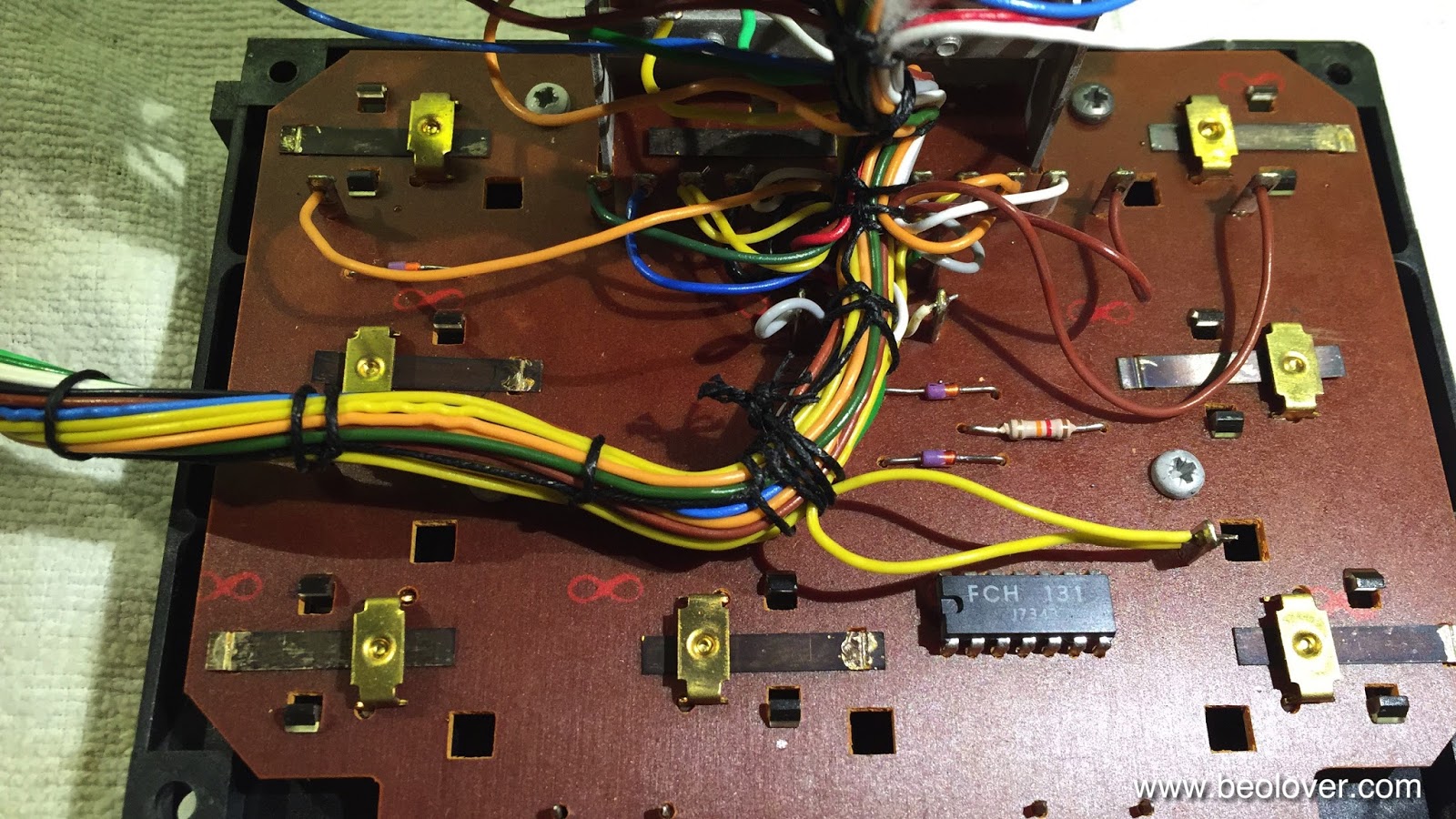
After this I unbolted the main PCB and flipped it over to have a look:
Then I prepared a replacement RPM relay based on a modern encapsulated Japanese relay:
I recently had the breakout boards professionally manufactured, so this part now looks very professional.
Here it is after installation:
Then I replaced all electrolytic capacitors on the board:
Not to forget the lone capacitor soldered to the solder side of the board. Before:
and after:
The remaining two capacitors (red dots) were on the power supply board:
I replaced those too:
Then it was time to see if the solenoid now behaved better. And it did. On to the keypad and the carriage switches.


Beogram 4000: Rebuilding the Arm Lowering and Tracking Systems

After fixing the broken off MMC cartridge mount in the Beogram 4000 that I am restoring right now, it was time to straighten out the not working arm lowering and tracking mechanisms.
This shows the solenoid and damper setup that controls the arm lowering process:
I extracted the damper and the linkages for cleaning and lubricating:
Unfortunately, the damper unit showed signs of human creativity:
The rubber washer that acts as a valve seal for the air release mechanism was missing. Instead a crudely shaped piece of transparency foil had been implanted preventing the damper from working properly:
Furthermore the damper cylinder was damaged causing the piston to get stuck. This meant that a replacement damper needed to be installed. Luckily, I recently bought a few parts units on ebay and craigslist, so I was able to extract a damper from a Beogram 4004. Here is a picture of the proper setup with a rubber washer at the end of the piston:
I lubricated everything and installed the new damper:
Then it was time to extract the damper to arm linkage. For this the sensor arm needs to be extracted. This shows the arms from the back:
The sensor arm is held in place by two screws and can easily be taken out to get at the linkage:
Here I found more signs of human interaction: The retaining washer that holds the linkage on its pin was missing. Luckily the spring that sits underneath was still there. I extracted the arm after pushing the sensor arm tube a bit out for access:
After cleaning and lubricating the bearing I put everything back together and added new retaining washer:
Then I put the arm back in and aligned everything that the arms were both perpendicular to the back of the enclosure.
The next step was to replace the tracking sensor light source with one of my SMD LED based light sources. This ensures long term stability of the tracking sensor sensitivity. Light bulbs tend to break and also change their light emission over time. This shows the part:
It is available to other enthusiasts. Just send me an email if you need one.
This shows the original tracking sensor light bulb housing installed:
And after extraction:
The tracking sensor aperture is visible. I installed the LED replacement part:
And then it was time to adjust the tracking mechanism, or so I thought. When I started the deck it turned out that the solenoid was not able to lower the arm. All it did was emit a loud hum while doing some rattling motions. Not good...this suggested that this deck has a bad reservoir capacitor for the 30V solenoid supply. So the next step is replacing the capacitors and get the power supply straightened out!