Featured Post

Beolover SyncDrive: DC Platter Motor Replacement for Beogram 4002 and 4004 (Type 551x and 552x)

Late Beogram 4002 and the 4004 (Types 551x and 552x), which have DC platter motors instead of the earlier synchronous AC motors usually suff...

Showing posts with label relubricating. Show all posts

Friday, March 15, 2019

Beogram 4004 (5526): Restoration of the Arm Lowering Mechanism and Exchange of Tracking Sensor Bulb with a LED Assembly

I started working on the Beogram 4004 (5526) that I recently received. As usual, I rebuilt the arm lowering mechanism and installed a LED assembly to replace the original tracking sensor incandescent light source.

This shows the arm lowering mechanism consisting of solenoid (left) and motion damper (right; to gently lower the arm once the solenoid activates):
I disassembled the setup
and cleaned away all the hardened lubricants. Then I re-lubricated everything and re-assembled the mechanism. The next step was to do the same for the linkage that connects the damper to the tonearm. To get to the pivot point of the linkage, the sensor arm assembly has to be taken out. This shows the arms from the back
and after removing the sensor arm:
After removing the retaining washer and the small spring that presses the linkage towards the sensor arm post (do not loose this spring if you try this at home, it has a tendency to vanish in 'small parts nirvana' and is never seen again...;-). This shows the removed linkage:
I cleaned, re-lubricated and reassembled. Then it was time to adjust the arms to be orthogonal to the carriage and parallel to each other:
This can be a bit tricky and listening to calming music is recommended.

After taking care of the arms, I exchanged the tracking sensor light source, which is originally a small bulb that frequently burns out, disabling the Beogram. Installing a LED ensures longterm stability. This shows the original part in place:
I removed the bulb housing revealing the aperture that controls the tracking feedback by varying the amount of light that hits the light sensor in the lower part of the housing:
This shows the original part and the Beolover replacement side-by-side:
The LED sits exactly in the spot where the filament of the original bulb is located. I installed the part and also replaced the sheet metal screw that holds the aperture in place on the lateral tonearm bearing with a stainless M2x16mm screw and a corresponding nut (this makes it much easier to properly lock the aperture position in place once the tracking feedback has been calibrated):
On to restoring the electronics of the deck.


Sunday, December 16, 2018

Beogram 4004 (5526): Restoration of Arm Lowering and Tracking Mechanism, Restoration of Original Solenoid Wiring and a New Reservoir Capacitor

The first focus on the Beogram 4004 (5526) that I am working on right now was, as usual, the restoration of the arm lowering and tracking mechanism. This restores in most cases the proper working of the solenoid/damper mechanism.

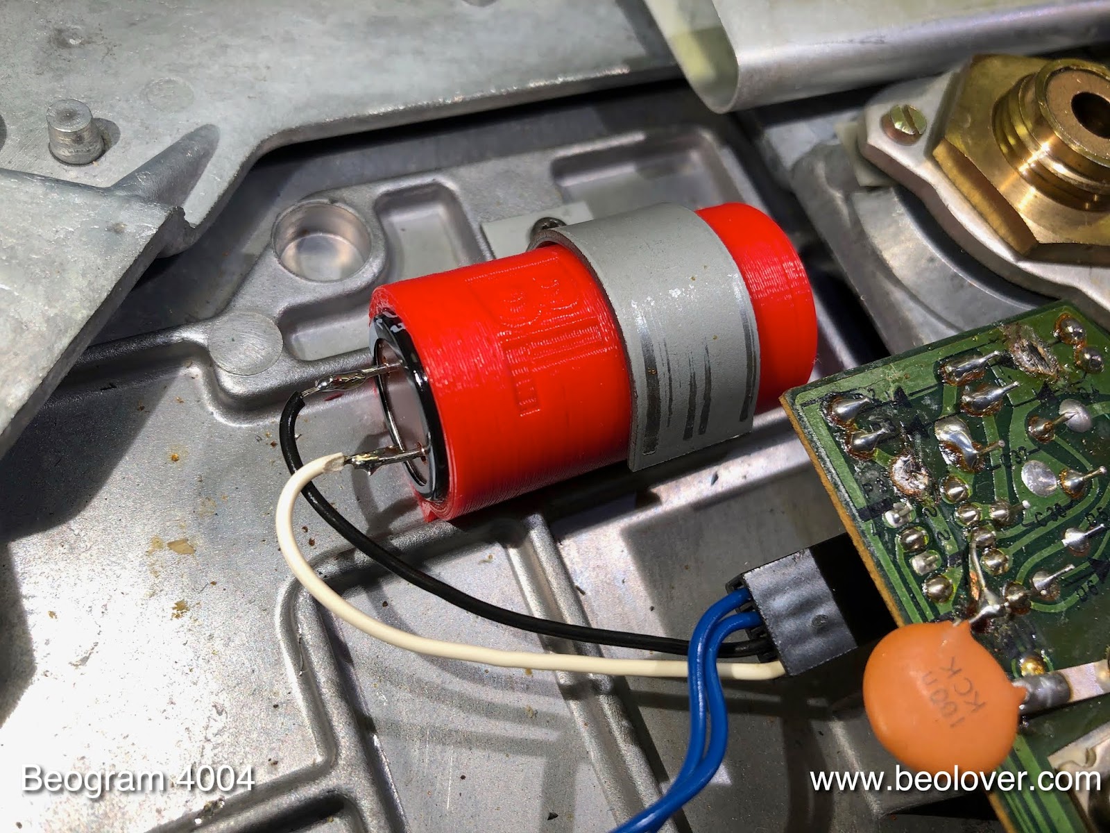
This Beogram came with a host of modifications that suggested that the previous owner had an issue with the solenoid function. He/she implemented a bigger reservoir capacitor and a thicker wire between main PCB and the solenoid board, obviously in an attempt to boost the power of the solenoid. All this was in vain, since the root-cause of the malfunction, hardened lubricants, was not addressed in the process.

This shows the modifications: Exhibit A, the added reservoir capacitance
and Exhibit B, the thicker (white) wire soldered directly to the board:
So the first step of this restoration was to reverse these efforts to restore the original wiring. Unfortunately, the previous owner cut the original control wire for the solenoid function pretty close to the plug insert and at the opposite end close to the solenoid board. Luckily he/she just left enough of the wire peeking out that I was able to remove some insulation with a razor blade for adding some more wire to restore the connections.

This shows the wire to board connector pin with cutoff wire.
I extracted it by pushing in the tab that blocks it from sliding out in the header. A bit of microsurgery with a razor blade allowed me to install a short jumper to be soldered to the solenoid wire:
Then I pushed the pin back into the header housing and soldered the wire in and insulated it with a short piece of almost color matched (always in style! - that is Beolove!) shrink tubing:
Then I did the same on the other end:
And so the connection was restored to its original design.
The next step was to remedy the capacitor mess. I removed everything and cleaned up the solder points on the board, and then installed the replacement:
At this point the mechanism still malfuctioned, i.e. the solenoid would briefly twitch when the deck initiated arm lowering at the 12" run in groove position. I measured the solenoid signal with an oscilloscope, just to make sure there was no electronics issue. The signal turned out to be a perfect close-to-30V-40ms pulse decaying into a ~2V constant voltage:
The purpose of this signal is to briefly power the solenoid at (or probably above) its limit to be able overcoming friction and the resistance of the damper etc...before settling into a much more 'comfortable' low power state that is just enough for keeping the springs in the arm lowering setup tensioned. At this point it was pretty much certain that hardened lubricants were the root cause of the problem.

This shows the solenoid/damper mechanism:
I removed the linkages and the damper for cleaning and relubrication:
During this procedure it became clear that the main cause of the issue was the solenoid linkage where the grease was so hardened that I needed to use a big screwdriver to carefully pry the linkage from its pivot point.
After reassembling the mechanism, the arm lowering process worked again. But I went on to complete the restoration process by removing the sensor arm to get to the linkage that links the damper and the tone arm. This shows the arms from the back:
and after taking out the sensor arm assembly:
I removed the linkage (careful if you try this at home - there is a small spring under the locking washer that can easily jump off to a four-dimensional coordinate point in the time-space continuum where it cannot ever be found again..;-):
I cleaned and lubricated the pivot point and put everything back together and reinstalled the arm assembly:
The final two steps in this restoration chapter are the replacement of the tracking system light bulb with an LED assembly, and the installation of an aluminum pulley to replace the cracking-prone original plastic wheel.
This shows the original tracking sensor setup:
I removed the light bulb housing
this reveals the aperture that controls the light amount that falls on the light sensor in the lower half of the sensor housing. This signal is used to form a feedback loop controlling the carriage motor during playback of a record in order to advance the arm as the needle is dragged towards the center of the record.

This shows the original bulb set-up with the Beolover LED based replacement:
The assembly is designed in a way that the SMD LED is in the spot where the filament of the bulb is located.

One weak spot of the aperture design is the sheet metal screw that is used to clamp the ring holding the aperture to the tone arm bearing. It is frequently loose and one cannot really tighten it. I usually replace it with a stainless M2x12mm flat socket head screw and a nut, which gives this setup a much better long term stability. 

This shows the LED assembly installed together with the new bolt:
On to the pulley. This shows the original one:
And the aluminum replacement (together with a new belt):
Allright...all good again in the arm lowering and tracking department! On to rebuilding the PCB.


Friday, May 11, 2018

Beogram 4004 (5526): Restoration of the Arm Lowering and Tracking Mechanisms

As usual I started the restoration of the Beogram 4004 (5526) that is currently on my bench with rebuilding the arm lowering and tracking mechanisms. This shows the solenoid and damper section of the turntable:
I removed the damper and the linkages for cleaning and re-lubrication:
After I put everything back together it was time to do the same for the linkage that connects the damper with the tone arm. This shows the backside of the arm assembly:
The sensor arm can be taken out by removing two screws that hold it to the floating chassis of the Beogram:
Once the arm is out, the linkage can be removed:
Care needs to be taken to not loose the small spring that sits under the retaining ring. After cleaning and lubricating the pivot point I replaced the sensor arm assembly and adjusted the the arms to be parallel and orthogonal to the carriage guiding rods.

The next step was to replace the incandescent light bulb that provides the illumination for the tracking sensor with an LED assembly. LEDs last much longer than light bulbs and this increases the long term stability of the restoration. This shows the original bulb housing in place:
I removed it, which exposed the tracking sensor aperture:
This shows the original bulb housing in comparison with my LED replacement assembly:
The LED is in the same spot as the filament of the bulb. Like all Beolover parts this part is available to other B&O enthusiasts. Just send me an email or use the contact form to the right.
I installed the LED assembly:
The final item to address was replacing the cracking-prone plastic carriage pulley with a machined aluminum part. This shows the original pulley in place:
And with the replacement and a new belt:
Beolovely! On to rebuilding the electronics!


Wednesday, February 14, 2018

Beogram 4000: Restoration of Arm Lowering and Tracking Systems

I started working on the Beogram 4000 from Germany. As usual, I restored the arm lowering and tracking mechanisms first. This shows the arm lowering solenoid and damper assembly:
I took the linkages and the solenoid out for cleaning and lubricating:
Once everything was back together clean and well-lubricated, it was time to take the sensor arm out to get to the damper-to-arm linkage, which is often stuck due to hardened lubricants. This shows the back of the arms:
Taking out the two screws at the bottom of the sensor arm assembly released the arm:
After removing of the locking washer the linkage can be taken out:
I cleaned the pivot bearing and put a bit of synthetic grease on the pin and then put everything back together. The next step was to align the arms that they are parallel to each other and orthogonal to the carriage rods:
The next step was to replace the cracked carriage pulley. This shows the original plastic pulley
and this the machined aluminum replacement:
Beolovely! Send me an email or use the contact form on the right if you are interested in getting such a pulley for your own Beogram. I'll be happy to get you in touch with Nick who provides them to the B&O community.
Finally, it was time to replace the original incandescent light bulb in the tracking sensor with a Beolover LED assembly. This guarantees long term stability. The bulbs often break and they are not available anymore. This shows the original setup:
The bulb is in the square black housing in the center of the photo. Taking it out reveals the tracking sensor aperture:
This shows the original bulb assembly in comparison to the LED replacement:
The LED sits in a spot close to the location of the filament of the light bulb. The blue trimmer that is integrated with the LED assembly allows the adjustment of the LED intensity, which is very practical when adjusting the tracking sensor feedback sensitivity. This shows the sensor implanted:
The LED light source is available to other B&O enthusiasts. Just send an email or use the contact form if you are interested.
The final act of this part of the restoration was to replace the old grimy sheet metal screw that clamps the aperture assembly to the tonearm assembly. This shows the original screw:
These are notoriously difficult to tighten and it is a great idea to replace them with a modern hex driven M2-12 mm bolt and a M2 nut, which can be tightened easily without changing the aperture alignment while doing so. On to rebuilding the electronics.