Featured Post

Beolover SyncDrive: DC Platter Motor Replacement for Beogram 4002 and 4004 (Type 551x and 552x)

Late Beogram 4002 and the 4004 (Types 551x and 552x), which have DC platter motors instead of the earlier synchronous AC motors usually suff...

Showing posts with label 1530JHBG4004. Show all posts

Saturday, May 26, 2018

Beogram 4004 (5526): Final Adjustments and Test Drive with Volker Kriegel on MPS

My current Beogram 4004 (5526) restoration project is coming to a close with making a few essential adjustments and tying up some loose ends. First, I replaced the original black plastic carriage pulley with a new one machined from aluminum:

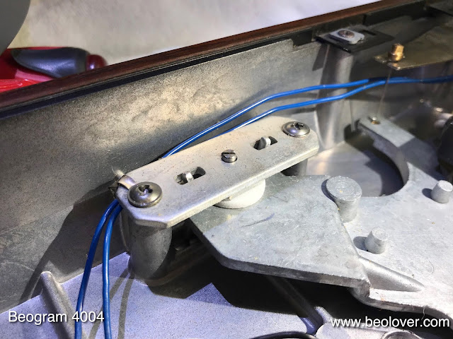
Then I replaced the metal sheet screw that holds the tracking aperture in place
with a nice stainless steel 2 mm bolt that can be tightened with a ball hex key...much better than the original Philips head to get it fully tightened to survive the rigors of shipping in the calibrated position. This shows the new bolt in place:
Then it was time to adjust the tracking feedback sensitivity:
The intensity adjust trimmer (small blue box) on the Beolover tracking sensor light source comes in handy for fine-tuning the mechanism after coarse adjustment of the aperture and sensor positions.

Then I adjusted the floating sub-chassis to be horizontal, did the arm to platter distance adjustment while making sure that the platter is flush with the surrounding aluminum panel. Then it was time to adjust the arm lowering limit that the needle would miss the ribs if it got accidentally lowered onto the platter without a record present. An important fail safe in case the record detection mechanism fails at some point in the future:

Before playing any turntable for the first time it is important to calibrate the tracking weight. I usually start out by replacing the flimsy locking clip that holds the counter weight adjustment screw in place with a nut to be able securing it permanently once the calibration is done. This shows the original condition:
and with the M3 nut in place:
Then I calibrated the weight adjustment wheel to be accurate around 1.2g, the tracking weight for most B&O cartridges:
This is preferably done with a small digital gauge, which are very precise these days due to advances in integrated sensor chip design (even if they are cheap).

After giving the aluminum surfaces a deep clean it was finally time to present this Beogram in its full glory and play it for the first time. I selected a recently acquired vinyl by the awesome German MPS label: "October Variations" by Volker Kriegel and the Mild Maniac Orchestra, which they recorded in 1977.
In my opinion this is among Kriegel's best albums for its consistency and wealth of great melodies and jazzy fusion sound. The second track on the first side "Ballad Garden & Palm Dreams" is my favorite...perfect for taking a Beogram DC motor apart or soldering SMD components...;-). I will now play this Beogram for a bit longer, and then it will be time for the trip home to its owner.


Thursday, May 24, 2018

Beogram 4004 (5526): Installation of A New Output Cable

After replacing the light bulb in the sensor arm with an LED assembly it was time to look into the RCA plug 'conversion' of this Beogram 4004 (5526). This shows the output cable in the condition when I received this Beogram:
Not a very inspiring sight. The blue and yellow leads are the Beolink signal lines that allow controlling the 4004 via a Beomaster 2400. We decided to return this 4004 to its original DIN7 output scheme. Originally the 4004 came with a convertible male DIN7 plug, which can be turned into a standard DIN5 by unscrewing the two pins that are extra in the DIN7 format. This shows a plug as seen on a 4004 I restored a few years ago:
The two outer pins were removed so that the plug essentially acted like a standard DIN5 phono output. Unfortunately, such DIN7 plugs are not available anymore. A solution I came up with is to install female DIN7 plug that has all the signals on it. If extended with a DIN7 cable it turns into a DIN7 male output that will properly work with a Beomaster 2400. Extend it with a DIN5 or a DIN5-to-RCA adapter and a standard non-B&O phono output is achieved.
This shows the female DIN7 plug during the installation:
Note that the leads need to be soldered in a mirrored pattern compared to that applied for a male DIN7 plug, since male-male DIN5 and DIN5-RCA jumper cables mirror the leads for symmetry reasons.

This shows the DIN7 connected to a DIN5-to-RCA jumper cable:
The system ground connection is on a separate wire (not visible on this photo) that it can be connected to the GND terminal of the RCA input amplifier.


Friday, May 18, 2018

Beogram 4004 (5526): Replacing the Light Bulb in the Sensor Arm with a LED Assembly

After replacing the transport lock bushings in the Beogram 4004 (5526) that is currently on my bench it was time to replace the light bulb in the sensor arm with a LED-based assembly. This shows the small bulb compartment pulled out of the sensor arm front:
The small flexPCB next to it is the LED circuit. Since modern high output LEDs have a much lower current draw than the original small light bulbs the LED circuit features a current bypass that adjusts the current to a level similar to the light bulb. This is important since there is a circuit on the main PCB that detects bulb malfunctions via current measurement, and the low current of LEDs would trigger this circuit, preventing the arm lowering mechanism from doing its job.

The flexPCB needs to be folded to fit into the bulb compartment. This shows the folded board next to the light bulb,
and installed in the compartment:
After replacing the compartment in the arm I tested the setup:
The B&O logo shows up with its usual red-orange glow. This is a result of using a warm white LED, which has enough red emission to properly illuminate the logo. The final step of any sensor arm light source replacement is measuring the sensor signal when the platter is spinning without a record on it. This shows the signal measured at the collector of TR3:
Each voltage drop corresponds to a black rib passing under the sensor. When everything is o.k. the drops should go close to 0V, while the amplitude should exceed 4V.  This Beogram 4004 passed the test with flying colors!


Monday, May 14, 2018

Beogram 4004 (5526): Installation of New Transport Lock Bushings

The Beogram 4004 (5526) that I am restoring right now had the orange type of transport lock bushings, which are prone to degradation. This was evident immediately after taking the Beogram out of the box, since there were telltale orange plastic fragments all over the place:
This shows the left transport lock without its bushing:

I removed the floating sub-chassis of the Beogram, which revealed the degraded remnants of all three transport lock bushings:
I vacuumed the enclosure, and then it was time to install the new 3D printed bushings:
Each bushing has two parts, one to be inserted from each side of the lock orifice. Like all parts featured on this blog they are available to other B&O enthusiasts. Order them directly via the Beolover Shapeways store. Six parts are needed for all three locks. This shows the lower part of the left lock:
And with the sub-chassis outfitted with a new bushing installed:
I also did this for the other two locks and then I replaced the top halves of the locks:
Now this Beogram can be shipped again without fear for damage due to loose transport locks.


Sunday, May 13, 2018

Beogram 4004 (5526): Restoration of DC Platter Motor

After replacing the incandescent bulbs in the RPM trimmer panel with LEDs it was finally time to restore the DC motor that drives the platter of this Beogram 4004 (5526). This shows the motor extracted from the Beogram:
Restoration of these motors requires infusing the brass sleeve bearings with fresh oil under vacuum. this requires complete disassembly of the motor:
The Oilite brass bearings are the two small donuts on the black pad. I immersed them in motor oil and pulled a vacuum:
Immediately, air bubbles emerged from the bearings as the vacuum drew the air from the empty pores of the Oilite material. This enabled motor oil to penetrate the bearing material, refilling the empty pores. After about 48 hrs the bubbling stopped, indicating that the infusion process was complete. At that point I removed the bearings from the jar:
I reassembled the motor and put it back into the Beogram. Then I installed my BeoloverRPM device to do a 24 hrs RPM stability test:
The BeoloverRPM device is able to log the RPM of the Beogram for extended periods, which is a great way to detect and diagnose RPM stability issues. It is available to other B&O enthusiasts. Just send an email or use the contact form on the right if you are interested. This shows the RPM graph as measured after about 24 hrs:
This is as good as it gets for the Beogram 4004, and we can conclude that this deck is back on track to spin vinyls for another 30 years.


Saturday, May 12, 2018

Beogram 4004 (5526): Replacement of Incandescent Bulbs in RPM Trimmer Panel with LEDs

Before the DC motor in a Beogram 4004 (5526) can be restored and tested it is a good idea to rebuild the DC motor control section of the main PCB and replace the incandescent bulbs in the RPM trimmer panel. The RPM stability of the platter drive system depends on all of these components. This shows the RPM trimmer panel as removed from the Beogram:


I removed the covers
and unsoldered the light bulbs:

Then I installed the LED replacement assemblies:
They are drop-in replacements for the light bulbs and include all necessary parts allowing running the LEDs from the 24V supply of the Beogram:
The covers fit like before:
This shows the 33 RPM LED in action:
The LEDs look very similar to an incandescent light bulb. This is the result of using red and green LEDs that are carefully tuned to resemble the emission spectrum of an incandescent light bulb.


Beogram 4004 (5526): Restoration of the Electronics

After rebuilding the arm lowering and tracking systems of the Beogram 4004 (5526) that I am restoring right now it was time to look into the PCBs and the reservoir capacitor. This shows the main PCB in its original condition:
This is a detail shot of the platter motor control circuit:
I replaced all electrolytic capacitors, the RPM relay and the RPM trimmers:
The replacement RPM relay assembly is available to other B&O enthusiasts. Just send me an email or use the contact form on the right. Once this was done, I moved on to the reservoir capacitor:

This Beogram was fitted with a single capacitance reservoir, which I replaced with a modern 4700uF capacitor outfitted with a 3D printed adapter that allowed bolting it into place using the original mounting strap:
The next step was the restoration of the output PCB. This shows the original board:
I replaced the electrolytic capacitors and the output relay:
And this concluded the restoration of the PCBs.


Friday, May 11, 2018

Beogram 4004 (5526): Restoration of the Arm Lowering and Tracking Mechanisms

As usual I started the restoration of the Beogram 4004 (5526) that is currently on my bench with rebuilding the arm lowering and tracking mechanisms. This shows the solenoid and damper section of the turntable:
I removed the damper and the linkages for cleaning and re-lubrication:
After I put everything back together it was time to do the same for the linkage that connects the damper with the tone arm. This shows the backside of the arm assembly:
The sensor arm can be taken out by removing two screws that hold it to the floating chassis of the Beogram:
Once the arm is out, the linkage can be removed:
Care needs to be taken to not loose the small spring that sits under the retaining ring. After cleaning and lubricating the pivot point I replaced the sensor arm assembly and adjusted the the arms to be parallel and orthogonal to the carriage guiding rods.

The next step was to replace the incandescent light bulb that provides the illumination for the tracking sensor with an LED assembly. LEDs last much longer than light bulbs and this increases the long term stability of the restoration. This shows the original bulb housing in place:
I removed it, which exposed the tracking sensor aperture:
This shows the original bulb housing in comparison with my LED replacement assembly:
The LED is in the same spot as the filament of the bulb. Like all Beolover parts this part is available to other B&O enthusiasts. Just send me an email or use the contact form to the right.
I installed the LED assembly:
The final item to address was replacing the cracking-prone plastic carriage pulley with a machined aluminum part. This shows the original pulley in place:
And with the replacement and a new belt:
Beolovely! On to rebuilding the electronics!