Featured Post

Beolover SyncDrive: DC Platter Motor Replacement for Beogram 4002 and 4004 (Type 551x and 552x)

Late Beogram 4002 and the 4004 (Types 551x and 552x), which have DC platter motors instead of the earlier synchronous AC motors usually suff...

Showing posts with label relay. Show all posts

Friday, January 24, 2025

Beogram 4000: Installation of a New Reed Relay

This is the third installment of my 'this Beogram keeps on giving' series about the Beogram 4000 from Australia that I have on my bench currently (in other words the Beolover is having some fun!..;-):

After fixing the tonearm wiring and the broken photocell in the sensor arm, this Beogram decided to give me a never experienced before new phenomenon:

After pressing OFF, the carriage returned home as it should, but after touching base, it decided to go back for an inch or so until it decided to finally come to rest. As if someone pressed ON again and then after a few milliseconds one of the < or > keys to bring the carriage to a premature stop before setting down on the record. Very strange! This was completely reproducible, i.e. happened every time I tried. Otherwise the deck seemed to perform normally.

After a bit of head scratching it occurred to me that maybe the 24V rail that controls the analog part of the control system did not shut down properly after the carriage triggered the off switch. I examined the reed relays that control the power in the Beogram 4000 and it became quickly clear that the one responsible for this 24V rail was stuck on closed.

The power supply setup in the Beogram 4000 can be a bit confusing, so a while ago I already made a schematic labeling some of the 'ingredients':

There are four reed relays (i.e. relays that are activated by a magnetic field generated by a surrounding coil to ensure galvanic separation of the circuits) that are controlled by two coils. These coils are the two big yellow items in the picture above. Each coil has two round passages into which the glass relay tubes are inserted. On either side the relays are connected with solder tabs that are inserted into the circuit board below and soldered to it on the backside. 
The upper coil relays control the 24V platter motor power and the power to the strobe light. Since the strobe light runs on about 90V that come from a dedicated secondary winding in the transformer this relay is fully insulated with shrink tubing.
The lower coil contains the 6V relay that controls the power to the digital control system inside the keypad cluster (basically the 'brain' of the 4000...;-), and the 24V relay that supplies power to the analog part of the control system (the 'muscle'...;-). 
This latter 24V relay is the one that was the root cause for the observed phenomenon. This was quickly confirmed with a multimeter, showing continuity across it even when the power plug was pulled.
Luckily there are replacements available. This shows a new Beolover Reed relay for Beogram 4000 Power Supply:
The relay exchange is slightly messy. This shows the original setup with the 24V relay still in place:

For removal of an old relay, it seems best to remove its solder tab on the left side first and then unsolder the other end of the relay from the solder tab on the right. This makes it easy to pull the relay out towards the left which is less obstructed. Be careful to not damage the very fine magnet wire that connects to the coils when you try this at home.
The first step is to remove the solder at the point where the relay connects to the tab with a solder sucker. Then the tab can be bend a bit away from the relay pin and then from the backside of the board the tab can be unsoldered and removed. The next step is to unsolder the other end of the relay and then it can be pulled out. Note that it is easy to damage the wire insulation of the red wires that are also attached to this tab. This shows the setup after removal of the relay tube:
Here a picture of the extracted original relay (top) together with the new one:
The new ones are slightly shorter but have longer pins. This makes installation relatively simple. The first step is to cut the right side pin to the proper length and then insert the relay followed by soldering it to the right tab. Then the left solder tab can be slid over the relay pin and pushed back into the PCB followed by soldering in place. The final step is soldering the relay pin to the tab and cutting the excess of the pin off. This shows the final result of the implantation:
After this procedure the Beogram performed again normally. On to finishing this project up!

Wednesday, October 11, 2023

Beomaster 5500 Type 2333: PCB Restoration Tasks

In the previous post I assessed the restoration tasks of this Beomaster 5500.

This post shows the work performed on the Beomaster 5500 circuit boards.

The first step was to remove the boards that will need to be worked on.
Here is a photo of the Beomaster 5500 prior to removing the boards.  The boards that will be worked on are labeled in the photo.


The following pictures are a sequence of Beomaster 5500 photos showing the boards being removed.


The last photo above shows the Microcomputer board removed...so I will start with that one.
Here are the before and after pictures of the Microcomputer board restoration.
There are just two electrolytic capacitors in this board.
There is also a CR2430, 3V Lithium battery.  It still measured 3V but it is still good to go ahead and replace the battery with a brand new one.


Note that for installing the new CR2430 battery I installed a battery holder for it.


The next board assembly is the Cooling Fan assembly.  It also has two electrolytic capacitors that I replaced.


The FM board came next.

Here is the FM board as it was received.


Here is the FM board after the electrolytic capacitors were replaced.


Here is the recapped Preamplifier board.  I didn't take a stand-alone before recapping photo of it so here are a couple of after recapping photos.  I replaced all of the signal path electrolytic capacitors with non-polarized, Nichicon audio capacitors.

Note that the highlighted Muting Relay had already been replaced so I didn't change that component.


The last Beomaster 5500 circuit board I worked on is the Power Supply and Output Amplifier board.
Here it is removed from the cabinet prior to any restoration work.


The white thermal compound on the heatsink assembly is just getting to the point where it feels a little bit dry.  For that reason I decided to remove the heatsink, clean the old thermal paste off and put new thermal protection on during re-assembly.

Here are photos of the heatsink removal and thermal paste cleanup.


Here is the Power Supply and Output Amplifier after I replaced the electrolytic capacitors, power supply relay and trimmer resistors for the output transistor bias.
There are two signal path blocking capacitors (2.2uF) for the audio signal from the Preamplifier board to this board.  I replaced those two capacitors with the same type I used in the signal path on the Preamplifier board.


Here is a closer photo of the new trimmer resistors.


The original power supply relay looked like this, de-soldered from the board.


The relay (RL1) still works but judging by the heat marks on the board and the fact that the Muting Relay (same type of relay) was already replaced...it is a good idea to go ahead and replace this relay.

I used a modern, enclosed relay.  It has two extra relay contacts that I had to cut off so that I end up with an identical mounting foot print.  I have used this replacement relay before on my own Beomaster 5500 and Beomaster 5000 amplifiers so I know it works well.


The next steps are to re-install the output amplifier board heatsink assembly then re-install the boards back into the Beomaster 5500 cabinet.

Sunday, May 24, 2020

Beogram 4002 (5513): Restoration of PCBs and RPM Adjustment Panel

A while ago I restored a Beogram 4002 DC platter motor for customer in California. Unfortunately, there were still noticeable RPM fluctuations at 45 RPM after re-installation of the motor. This usually points towards an oxidized RPM relay. They tend to go bad on 45 first, since in most Beogram they stay put at 33 RPM and are only rarely switched to 45. This allows oxide to grow on the 45 RPM contact terminals. My customer decided to let me restore the rest of the 'RPM chain', and I recently received the PCBs and RPM adjustment panel of this Beogram.

I started with the main PCB:
I replaced all electrolytic capacitors and then installed a new RPM relay and new RPM trimmers. This shows the original parts:
And the new ones:
Then I installed the board and tested the record detection sensor signal at the collector of TR4 with an empty platter turning:
This was a pretty weak signal, an indication that TR4 had lost some of its gain (Hfe). This shows the original TR4, a BC138C with its 1MOhm biasing resistor in the back:
I installed a new 2N5089 high-gain transistor with an Hfe of about 750. Correct biasing of this transistor requires replacing the 1MOhm biasing resistor with a multi-turn 5MOhm trimmer, which I first installed on the solder side, that I could adjust the collector voltage to the specced 4V:
Then I put it 'below deck' in the original place of the resistor:
This is the sensor signal I measured on the empty platter after this procedure:
The valleys (that correspond to the black ribs on the platter) now go close to 0V, which is what the service manual prescribes. 
This concluded the main PCB restoration:

On to the output PCB, which also has an often oxidized relay. this shows the original board:
I installed a new relay, replaced the capacitor that is responsible for the time delay for actuating this relay after the needle sets down on the platter, and I added a switch that allows the convenient connection of system and signal grounds in case there is a hum issue:
The remaining task was replacing the incandescent light bulbs that illuminate the RPM panel scales with LED fixtures. This alleviates the remaining cause for RPM fluctuations which can also be caused by thermal changes due to the heat emanating from the light bulbs. This shows the original bulbs installed:
I replaced them with LED boards:
and put the light shields back on:
Now it was time to install everything in one of my 4002s for testing. This shows the 33 RPM LED in action:
The red-green LEDs that I use for these panels allow to give them a realistic incandescent-like sheen, and also properly illuminate the red indicator. Beolovely!
On to testing the RPM performance with the BeoloverRPM device:
The BeoloverRPM device is able to log the RPM over extended periods of time. This is the curve I measured over about 24 hrs at 45 RPM:
This is as good as it gets with the DC motors, i.e. this Beogram should be back in business!


Sunday, March 24, 2019

Beogram 4004 (5526): Restoration of PCBs and Reservoir Capacitor

After the restoration of the arm lowering mechanism of the Beogram 4004 (5526) that I am restoring right now, it was time to look after the PCBs and the reservoir capacitor. This shows the main PCB in its original condition:
and a detail shot of the 'RPM control' section:
I replaced the electrolytic capacitors, the RPM relay and the RPM trimmers. The original electrolytic capacitors often fail at this point in time, and the relay/trimmers are often oxidized, which can cause platter RPM fluctuations. This shows the rebuilt board
and the RPM section:
I did the same to the output/remote control PCB:
This is a detail shot of the output section:
I replaced the capacitors and the relay, and also added a switch that allows connecting the system and signal grounds together if there is a hum issue (often an issue when using RCA adapters without ground breakout):
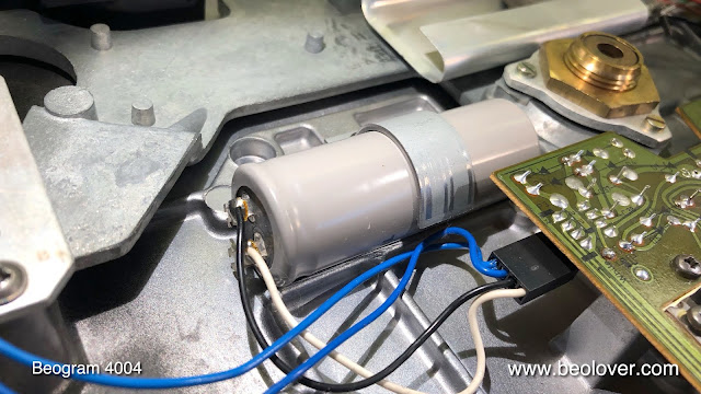
The final step of this part of the restoration was to replace the reservoir capacitor. This shows the original unit:
And the modern replacement:
On to the RPM LEDs and the platter motor restoration!