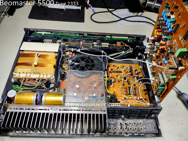
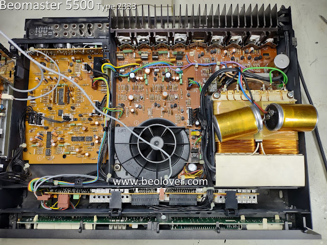
This project is a restoration of a Beomaster 5500 from an original owner.
It is an analog audio component that has a digital control system for operating it (Master Control Panel MCP5500).
Here is the initial assessment of its condition.
It is a little dusty but that isn't a problem as I will be cleaning it as I do the restoration work.
The shiny aluminum top trim piece is pretty marked up. That is due to the other Beosystem 5500 components stacked on top. B&O designed these components to be stacked so it isn't a surprise to see the tops showing signs of wear like this.
The Beoparts store sells replacement aluminum trim to restore the cabinet if someone wants to make it new looking again :-).
Here is the back view of the cabinet.
A feature that I really love about the B&O cabinet design on these is how easy it is to open it up for servicing.
Two screws are loosened (not removed...and lost). That allows two locking brackets to be raised up and held in place by tightening the screws again.
The unlocked cabinet top then slides back a little and lifted off.
Here is the Beomaster 5500 with the cabinet top removed.
Here is the Beomaster 5500 with the cabinet top removed.
The five highlighted screws are removed next to allow the AM/FM Stereo Tuner board to lift up into service position.
Some of the screws were loose so I suspected this Beomaster had been in for some service at some point in its history.
Some of the screws were loose so I suspected this Beomaster had been in for some service at some point in its history.
Flipping the unit around I could see that the audio muting relay has been replaced already.
That is a component I would have replaced if it was still original.
The same type of relay was used for the power supply rail voltages. They get disconnected when the Beomaster 5500 is in Standby mode.
That relay is still original so I will be replacing that one.
Next, I removed the translucent, plastic air duct the helps cool the output amplifier components.
Everything looks good so far.
Now to see if the Beomaster 5500 can be turned on and switch through its operation modes.
To do that I will use my own MCP5500 (Master Control Panel).
Unlike the Beomaster 5000, the Beomaster 5500 does not have a control panel built into it.
There are a couple of push buttons on either side of the front panel to turn the Beomaster on and off...plus some really minimal source switching. You have to use the MCP to really operate this receiver.
Plugging the Beomaster 5500 in, it goes into Standby mode, which is what it is supposed to do.
I exercised the operation of the Beomaster with the MCP and could hear the relays engage when I went out of Standby mode.
It appears that all of the selectable functions work so I am ready to move forward and start the restoration.
From what I have seen so far I will replace all of the old electrolytic capacitors with new capacitors.
I will replace the power on relay.
I will also re-flow solder joints on the boards. That will guard against any unseen breaks in the electrical paths.
The Beomaster has a small, lithium battery for its built in memory to remember user settings.
I will replace that battery.
The thermal compound on the output amplifier heatsink looks like it is still soft (not dried out).
So I probably will leave that as it is unless I see the amplifier getting too hot during testing.
This Beomaster 5500 cabinet is missing its rubber cabinet feet. That is pretty common and expected.
I will replace those feet with a set that Beoparts reproduces. Typically all of the audio components in these B&O systems (5000, 5500, 6500, 7000) have missing or broken cabinet feet.
Once I get the restoration work complete on this receiver I will be able to test it using my various Beosystem 5500 components and the MCP5500.


No comments:
Post a Comment
Comments and suggestions are welcome!