Featured Post

Beolover SyncDrive: DC Platter Motor Replacement for Beogram 4002 and 4004 (Type 551x and 552x)

Late Beogram 4002 and the 4004 (Types 551x and 552x), which have DC platter motors instead of the earlier synchronous AC motors usually suff...

Showing posts with label record. Show all posts

Wednesday, January 22, 2025

Beogram 4000: Installation of New Beolover Sensor Arm Photocell

The Beogram 4000 from Australia that I am restoring right now kept on giving! After I fixed the tonearm wiring to get both stereo channels working further tests revealed that it would not recognize the absence of a record and eagerly put down the arm onto an empty platter. Luckily I had already adjusted the arm lowering limit and so nothing happened to my MMC20 EN cartridge.

Ignoring the absence of a record is a telltale sign for a dead photocell in the sensor arm. The circuitry recognizes a dead sensor arm bulb and shuts down arm lowering if this is detected. However, a damaged photocell is not recognized. It simply simulates a black surface on the platter, and so the arm lowers.

I pulled out the sensor compartment and closer inspection revealed that one of the two electrodes on the photocell had disconnected. It looked like this:

This photo is from an earlier post about this type of issue, where the photocell of a Beogram 4002 had come apart. This earlier post reports about my initial development efforts aiming for a suitable replacement of the original photocell. 
I removed the photocell fragments:
And then it was time to install the newly designed Beolover Sensor Arm Photocell for Beogram 4000, 4002, and 4004. It is available via the Beolover Store. This shows the business side of the part:
At the front end (left) there are three photodiodes in parallel (to ensure sufficient current generation). On the back end (right) a 3D printed alignment piece is installed that helps keeping the cell properly oriented and in its proper spot relative to the lens in the sensor arm compartment.
This shows the backside with the two contact leads:
This is a real photocell like the original. It puts out ~0.45V photovoltage when exposed to sufficient light:

This means that unlike with other photocell replacement schemes no circuit modification is necessary. This is a direct drop-in part that replaces the original photocell (B&O part 8760002)
Installation is simple: Just stick the leads into the holes in the small circuit board attached to the sensor arm compartment (it is a good idea to use a solder sucker to remove the solder from the solder pads on the backside of this board to ensure the holes are open after unsoldering the original cell):
Then insert the photocell into the small compartment where the original cell was located and align the small protrusion on the alignment piece with the hollow rivet that holds the PCB to the plastic part: 
Then press the back end down until the frontend with the photocells hits the roof of the compartment:
Then the leads can be soldered to the pads on the underside of the PCB:
This shows the underside with the red and blue photo cell leads attached:
I tested the new cell with my oscilloscope, which was connected to the collector of the sensor transistor 1TR14 whose collector DC bias was adjusted to be 1.8V:
 
The photocell yielded a strong 2.5V amplitude signal over the rotating platter. More than spec. So all is good again in the record detection department.


Tuesday, March 12, 2024

Beogram 5500 Type 5943: Operational Again

This Beogram 5500 turntable is playing records again.  I connected it to its Beomaster 5500 unit and fitted it with an MMC-2 phono cartridge.


The Beogram sounds great and the remote control functionality with the Beomaster works perfect.
These Beosystem 5500 components are ready to return home to their owner.

To get to this point from the previous post I had to go through the Beogram 5500 service manual adjustments.

The set down point and the platter speeds were the only adjustments that were out of range on this turntable.  However, there was a problem with the platter motor making an audible racket as it turned.
The sound is similar to Beogram 4002/4004 platter motors as they age and their oilite bearings dry out.
I am not setup to re-infuse the bearings right now the way Beolover restores the Beogram 4002/4004 motors. I will save this motor for restoration later and in the meantime use a spare Beogram 5500 platter motor.


Bang & Olufsen used this same 12VDC MMX-4H2RPB motor as the platter motor for a number of their turntables.  Both tangential arm and radial arm turntables from around 1984 and on. 

The replacement motor is nice and quiet so the platter rotates silently now.

For the speed adjustments there are two trimmer resistors on the Beogram 5500 controller board.


To check the speed setting I used the new Beolover RPM tool.
In order to put the Beogram 5500 into record play mode so I could measure the platter speeds I placed a 45 RPM record on the platter then paused record play.  The 45 RPM record leaves the edges of the platter with the markings exposed for the Beolover RPM tool to measure with.


The tonearm set down point for record sizes 17 cm (~7 inch) and 30 cm (~12 inch) were initially off the mark on this Beogram.  

The service manual specifies that the 17 cm set down point should be adjusted first, then the 30 cm set down point.


For the 17 cm set down point adjustment there is a black, plastic eccentric disc that moves the set down position in or out as shown in the following picture. The disc can be rotated with a flat head screwdriver.


For the 30 cm set down point adjustment there is a metal lever whose position is moved with a white, plastic (nylon) adjustment screw.  After the position is moved, a locking screw is tightened to ensure the lever position doesn't change.


Here is the 30 cm set down point after the adjustment.


Although I didn't have to adjust the Beogram 5500 record tracking sensitivity it is worth noting that I checked it.
That adjustment appears more difficult on this type of Beogram than the Beogram 400x and 800x turntables. On those turntables it is easy to disable the platter motor function and move the arm to a test track where the arm is lowered.  Once lowered, the platter is manually rotated to check the record tracking.

On the Beogram 5500 while the platter drive can easily be disabled by removing the platter belt, manually getting the arm to a test track to test the sensing of the arm position seemed difficult.
Manual operating the platter to control the arm movement and set down are rather unclear.

For this Beogram 5500 I put on a test record with the platter functional and observed the record tracking by viewing the servo motor advancement from the rear of the Beogram.


From this vantage point I was able to check platter revolutions with regard to the Servo Motor advancing the drive pulley.

I could see that this Beogram Servo Motor started advancing the arm within 2 turns of the platter after the initial set down. That is setting down on a music track...not setting down on the lead in groove.
Once set down, the Servo Motor advanced the arm every revolution of the platter.

The rest of the adjustments like the audio signal muting, arm alignments and suspension were all good so I was comfortable to install a good MMC-2 phono cartridge for the listening test.

Monday, May 2, 2022

Beogram 4000/2/4: Update of Sensor Arm LED Assembly. No More Crumbly Flex-PCB Mess!

I recently re-designed the sensor arm LED assembly for Beogram 4000, 4002, and 4004. The previous version using a flex-PCB proved too difficult to install for some customers. My updated design is based on a small 'hard' PCB that fits precisely into the bulb compartment and uses an insert for proper positioning (it is important that the LED is approximately in the spot the lightbulb filament occupied).

This shows the new components:

And here a still from the video below that shows the LED 'in action':

The LED board produces a nice focused spot on the platter and also the B&O logo is lit up properly in the correct hue.
I updated my original sensor arm video and it shows now how to install these parts in Beogram 4002 and 4004. The video also shows how to update the record detection circuit. It usually benefits from installing a new transistor for amplifying the sensor signal. The procedure for Beogram 4000 is similar, but naturally the board looks a bit different, i.e. you will need to find the transistor for the sensor signal amplification via the service manual. Enjoy!:


Saturday, April 13, 2019

Beogram 4004 (5526): (New Beolover Video!) Exchanging the Sensor Arm Light Bulb with an LED Assembly

After getting the DC platter motor finally to run properly, it was time to exchange the last light bulb in the Beogram 4004 (5526) that I am restoring right now, the sensor (detector) arm bulb with a LED. This process has still been a bit 'experimental', but I think we finally have come to a stable process that should be relatively easy to replicate by other B&O enthusiasts around the world. So I decided it was finally time to make a video that outlines this process for those who would like to implement our LED assembly (send an email or use the contact form on the right if you are interested in getting the part). This shows the LED assembly next to the bulb compartment in the sensor arm:
The video discusses the detector circuit, how to upgrade it for reliable performance, and how to install the LED assembly. Enjoy!

Thursday, February 21, 2019

Beogram 4004 (5526): Replacement of Sensor Arm Bulb with a LED

After restoring the record detection circuit and the PCBs it was decided that the sensor arm light bulb should also be replaced with a LED to ensure operability of the deck down the road. These old light bulb like to fail, especially during shipping, i.e. it is a good idea to replace the bulbs with LEDs when restoring a Beogram. This shows the original light bulb in the sensor compartment together with the replacement flexPCB-based LED assembly:
I removed the bulb and inserted the LED board, which folds snugly into the compartment:
This shows the LED in action:
The LED is a warm-white type, i.e. there are enough red photons to ensure a properly colored B&O logo.
Whenever the light source in the sensor arm is replaced, the sensor response needs to be checked. The signal strength is highly dependent on the location of the light source in the compartment. The signal at the collector of the signal amplifying transistor TR3 needs to be close to 6V or better. This shows the measurement I made after the installation:
This Beogram record detection circuit is now operating better than spec (7.9V amplitude), i.e. we can confidently press the START button. 


Monday, January 7, 2019

Beogram 4004 (5526): Replacement of Sensor Arm Light Bulb with an LED Assembly

When I restore a Beogram I usually exchange the incandescent light bulbs with LED assemblies. LEDs last much longer and yield a constant light output over their lifetime. This post discusses the replacement of the sensor arm light bulb of the Beogram 4004 (5526) that I am currently restoring. The bulb and sensor compartment can easily be pulled out of the aluminum profile (if your fingernails are not cut too short..;-):
The flex-PCB based LED assembly is shown on the right. It uses a warm white LED which produces enough red photons to make the B&O logo at the end of the sensor arm light up red. I unsoldered the bulb and extracted it. The LED assembly folds into the vacated bulb compartment:
This shows the assembly in action:
Whenever the light source is replaced in the sensor compartment, the record detection circuit needs to be checked for proper functioning. A stylus crashing onto the platter without a record present can get expensive...
The first step is ensuring that the collector of the sensor amplification transistor TR3 has the prescribed 4V DC without a sensor signal present. Usually, it shows a lower voltage due to the design of the circuit that relies on biasing TR3 via a single 1MOhm resistor connected to the collector. Due to variations in the transistor gain Hfe between individual transistors of the same type, this biasing scheme is not reliable since the base bias will vary with each transistor. This can be remedied by replacing the biasing resistor with a 2 MOhm multi-turn trimmer and then adjusting it for 4V at the collector. This is shown here:
I usually install the trimmer on the solder side of the PCB so one can adjust it while the board is powered up, and then I unsolder it and install it on the component side.

Once 4V are established, it is time to measure the sensor signal at the TR3 collector when the arm is over the rotating platter. For that a jumper wire needs to be soldered to the collector and the platter installed. This shows the oscilloscope trace measured after the LED was installed:
The amplitude should be between 5 and 6V, and the valleys should go all the way to 0V. This Beogram passed with flying colors. If the trace does not hit 0V, then usually the LED (or light bulb) does not sit in the right spot. This can sometimes be a bit tedious, but after a few trials one usually can achieve a trace like the one shown here.


Tuesday, December 4, 2018

Beogram 4004 (5525): Replacement of Sensor Arm Bulb with LED Assembly and Calibration of Sensor Amplification Circuit

A Beogram 4004 that I restored a few years back returned to my bench for some TLC/adjustments. Along with the adjustments it was decided to also update the restoration to the latest Beolover standard, i.e. the sensor arm bulb needed replacement with an LED assembly, which was not yet available during this Beograms's first visit.
This shows the sensor arm bulb cabinet pulled out together with the flexPCB based LED replacement circuit:
After extracting the bulb I installed the LED assembly and fired it up:

The LED that is used on the board is a warm white LED, i.e. it has enough red emission to make the B&O logo light up nicely.
The next step of this procedure is to adjust the biasing of TR3 properly. TR3 is responsible for amplifying the weak signal of the photo diode that is in the sensor arm. By design the base of this transistor is biased with a 1MOhm resistor (R26) pulled up by the collector. Unfortunately, this biasing scheme depends on the transistor gain Hf, which can vary quite drastically across several transistors of the same production run.
As a consequence one rarely finds a Beogram 4002 or 4004 that has the proper manual-specified 4V at the collector. This issue can be corrected by adjusting R26 until 4V are present. This can be done by replacing R26 with a 2MOhm multi-turn trimmer, and adjusting for 4V. This shows the trimmer installed from the solder side of the board that it can be adjusted while the Beogram is running:
After adjusting the collector voltage to be 4V I unsoldered the trimmer, and installed it from the component side:
After this it was time to measure the sensor signal at the collector of TR3:
The amplitude of the signal is 6.3V, exceeding the manual specified 6V, which is good. It should not be smaller, but a bit larger is o.k. Important here is also that the signal drops (that correspond to the passing of a platter rib) go all the way down to 0V. 
This result indicated that the sensor circuit was working properly, i.e it was time to test with and without a record present. All went well. I will play it a bit more and then it will be time to send it back to its owner!


Friday, May 18, 2018

Beogram 4004 (5526): Replacing the Light Bulb in the Sensor Arm with a LED Assembly

After replacing the transport lock bushings in the Beogram 4004 (5526) that is currently on my bench it was time to replace the light bulb in the sensor arm with a LED-based assembly. This shows the small bulb compartment pulled out of the sensor arm front:
The small flexPCB next to it is the LED circuit. Since modern high output LEDs have a much lower current draw than the original small light bulbs the LED circuit features a current bypass that adjusts the current to a level similar to the light bulb. This is important since there is a circuit on the main PCB that detects bulb malfunctions via current measurement, and the low current of LEDs would trigger this circuit, preventing the arm lowering mechanism from doing its job.

The flexPCB needs to be folded to fit into the bulb compartment. This shows the folded board next to the light bulb,
and installed in the compartment:
After replacing the compartment in the arm I tested the setup:
The B&O logo shows up with its usual red-orange glow. This is a result of using a warm white LED, which has enough red emission to properly illuminate the logo. The final step of any sensor arm light source replacement is measuring the sensor signal when the platter is spinning without a record on it. This shows the signal measured at the collector of TR3:
Each voltage drop corresponds to a black rib passing under the sensor. When everything is o.k. the drops should go close to 0V, while the amplitude should exceed 4V.  This Beogram 4004 passed the test with flying colors!


Saturday, April 7, 2018

Beogram 4000: An Entertaining Afternoon Exploring the Record Detection Circuit

While exploring an issue with the differential stop circuit of the Beogram 4000 that I recently finished restoring, I noticed another strange issue: While record detection worked at the 12" (LP) set down point, it often failed at the 7" (singles) point, i.e. when starting the deck without a record on the platter, it would pass by the LP point, but then set down at the singles point.

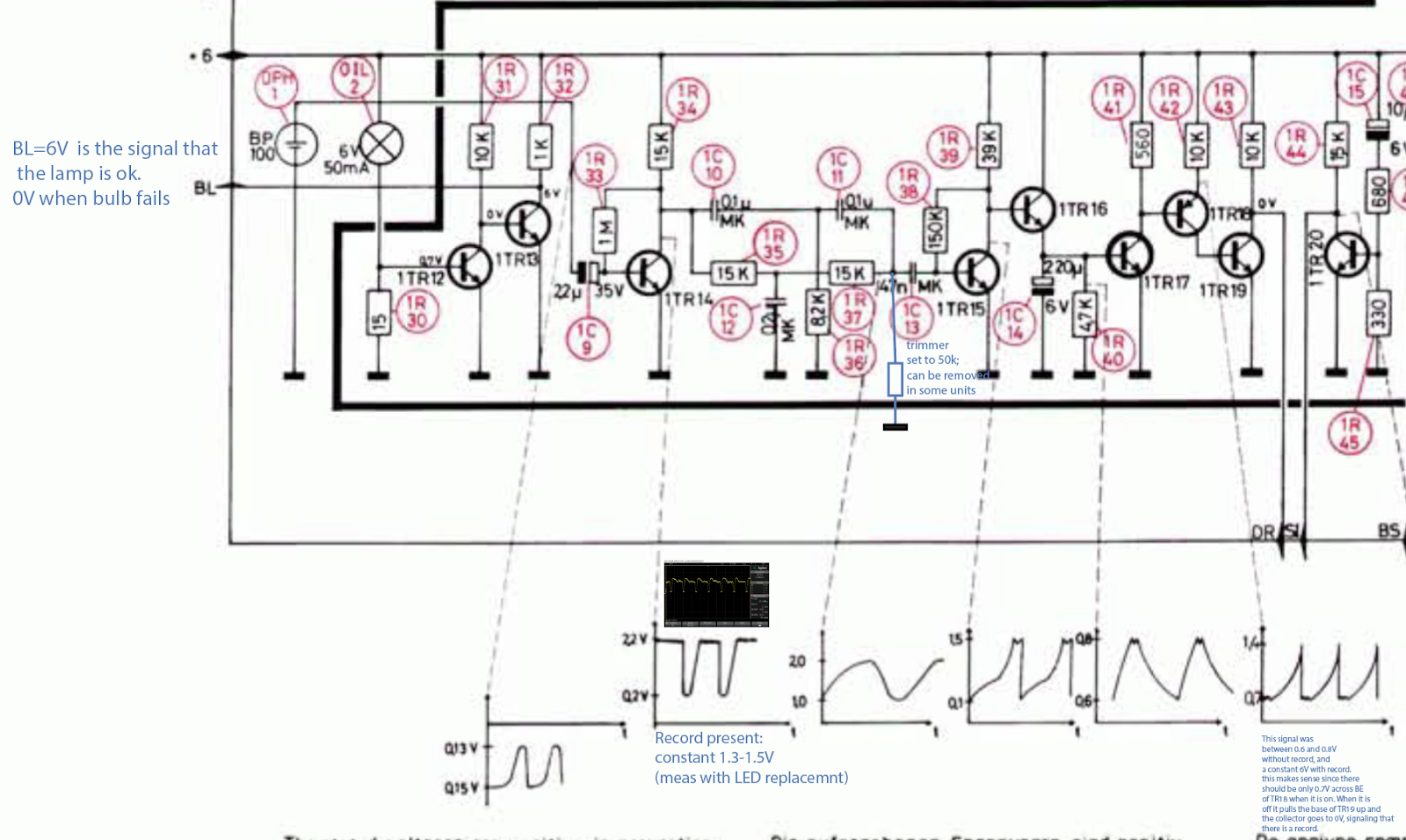
But let's first have a look at the circuit diagram: This shows the relevant section covering the detection system:


The sensor signal from BP100 on the left is fed into the base of TR14 via C9. TR14 provides an initial amplification of the weak sensor signal that then is processed further into a digital output signal for the control system. The signal is filtered in a RC network and fed through TR15,16,17,18 which essentially provide current and signal inversion resulting in a digital output signal from the collector of TR19, which is the "DR" input to the control logic in the keypad. DR is 6V if a record is present and 0V if there is no record on the platter. 
So the first step of my investigation was to measure IN and OUT signals of the circuit to see if the issue is in the circuit (and not in the control logic). This is what I got:
The green trace is the amplified sensor signal at TR14. We see the usual oscillation as the ribs on the platter pass underneath the sensor. These oscillations are as specified (~0.2-2.2V), i.e. my LED replacement of the light bulb was still working fine (as expected!...;-). The yellow graph is the DR signal. We see that in the beginning as the sensor arm passes the small gap between home position and platter the signal is 6V as it should be (the gap has no ribs, i.e. it looks like a record to the detection system). Then, when the oscillations start on the green curve (sensor is now over the platter), there are a few strange oscillations in the DR signal before it settles into the prescribed 0V indicating that there indeed is no record. However, as the carriage travels further in, these oscillations start again and then even temporarily give way to a constant 6V stretch before the oscillation starts again. Absolutely not like it should be! When everything works properly the yellow signal stays solidly at 0V until the carriage returns home. 
After having a bit of a think I concluded that TR19 was not providing enough current to the three logic gates that are fed with the DR signal. From the FHC131 datasheet I learned that these ancient gates take an impressive 2 mA per input when they are pulled low. So it seemed that TR19 was not fully on, causing its collector to drift towards 6V. The oscillation is probably a result of the fact that when CE goes high resistance, the BE current is concurrently reduced allowing the voltage from the (feeding) transistor TR18 to recover until the process starts anew.
After this illuminating moment I wondered about the root cause of this issue. Often one can find circuit problems by simply looking at the circuit to see anomalies like heat traces or the like. In this case my eye fell on the strange trimmer that one finds soldered to the main board on the solder side in most Beogram 4000s:
It is not on the circuit diagram. It is a 50k trimmer that connects R37/C13 to GND (I added it to the above diagram in blue). I checked the four 4000s that I have currently around, and their trimmers were all set to the maximum 50k value...somehow this suggested that whoever adjusted them seemed not to think much of them, trying to reduce their current draw as much as possible. At this point I am a bit mystified why the trimmer was added as an afterthought by the designers...there must have been some issue with the circuit under some circumstances, maybe a parts tolerance issue.

Anyway, experimentation and hunches often yield a fix and so I hooked up the oscilloscope to the collector of TR15 and measured with and without the trimmer connected. Disappointingly the curves looked very similar like this:
About what the diagram above suggested. This frustrated me a bit, but there was no stopping at this point and I marched on, connecting the oscilloscope to the collector of TR18, which feeds the base of TR19, i.e. if TR19 has trouble staying on while delivering 6 mA, there needs to be a difference in the TR18 output. And bingo, the trimmer made a big difference there. This is the signal with trimmer:
We see big spikes towards 6V, while the diagram suggests spikes no larger than 1.4V. I took the trimmer out and measured this:
Very small spikes, meaning that in this case TR19 was basically permanently on since TR18 stays fully on, i.e. TR19 should have no trouble providing 6 mA into the gates of the control system. And indeed, with the trimmer gone, the 4000 record detection mechanism started working very reliably. So the lesson learned here is to not only check the signal at TR14, but also at TR18/19 to make sure that the DR signal is stable. Alright, time to enjoy another record one this lovely Beogram 4000! Let's see if that was the last act of this eventful restoration.

**************************Note added in proof***************************************
The great Dillen of Beoworld.org sent me a message after I posted this. He indicated that this trimmer was added to the 4000 circuit as a way to adjust the sensitivity of the circuit due to the advent of transparent vinyl records. If there is a transparent record, the ribs of the platter are visible to the sensor at varying 'contrast' depending on the color and widely varying translucency of such records.
So I went ahead and experimented a bit more using a translucent red and completely clear record. This particular Beogram 4000 was able to detect both without any ambiguity with trimmer absent. 
However, this does not mean that this is the case for all Beogram 4000s, since the sensor circuit is designed with analog amplification stages that are biased using a single BC resistor. This makes the gain dependent on the individual current gain value (Hfa) of each transistor, which can vary significantly, even if the transistors are from the same production run. So this issue is something to keep in mind when working on the 4000 and a verification of proper detection of clear records should be part of the 'standard restoration repertoire'. The joyful exploration of analog control systems continues!..;-)



Saturday, March 17, 2018

Beogram 4000: Replacement of Sensor Arm Light Bulb with an LED

The final incandescent bulb to be upgraded with an LED in the Beogram 4000 that I am restoring right now was the one in the sensor arm. This LED is the most difficult to replace due to the compact dimensions of the compartment in which it is located. This required the design of a flex PCB based solution since this LED not only needs a current limiting resistor, but also a current bypass to simulate the presence of a light bulb drawing a much more significant current than a modern LED. This current is used by the control system to detect if the light bulb is working, i.e. the LED setup needs to draw a similar current. This shows the bulb compartment pulled out of the sensor arm:
I removed the bulb. This shows the bulb together with the already folded LED assembly:
Then I installed the flex PCB into the bulb compartment. This shows it powered up:
The warm-white LED emits enough red photons to properly light up the B&O logo like the original bulb.
Whenever the sensor arm light source is replaced the record detection circuit needs to be tested to make sure the absence of a record is properly detected. This shows the signal measured at the collector of TR14, which amplifies the sensor response for the control system:
It is as specified in the manual, having an amplitude of about 2V spanning from 0.2 to 2.2V. All good in the sensor department!