Featured Post

Beolover SyncDrive: DC Platter Motor Replacement for Beogram 4002 and 4004 (Type 551x and 552x)

Late Beogram 4002 and the 4004 (Types 551x and 552x), which have DC platter motors instead of the earlier synchronous AC motors usually suff...

Showing posts with label photocell. Show all posts

Wednesday, January 22, 2025

Beogram 4000: Installation of New Beolover Sensor Arm Photocell

The Beogram 4000 from Australia that I am restoring right now kept on giving! After I fixed the tonearm wiring to get both stereo channels working further tests revealed that it would not recognize the absence of a record and eagerly put down the arm onto an empty platter. Luckily I had already adjusted the arm lowering limit and so nothing happened to my MMC20 EN cartridge.

Ignoring the absence of a record is a telltale sign for a dead photocell in the sensor arm. The circuitry recognizes a dead sensor arm bulb and shuts down arm lowering if this is detected. However, a damaged photocell is not recognized. It simply simulates a black surface on the platter, and so the arm lowers.

I pulled out the sensor compartment and closer inspection revealed that one of the two electrodes on the photocell had disconnected. It looked like this:

This photo is from an earlier post about this type of issue, where the photocell of a Beogram 4002 had come apart. This earlier post reports about my initial development efforts aiming for a suitable replacement of the original photocell. 
I removed the photocell fragments:
And then it was time to install the newly designed Beolover Sensor Arm Photocell for Beogram 4000, 4002, and 4004. It is available via the Beolover Store. This shows the business side of the part:
At the front end (left) there are three photodiodes in parallel (to ensure sufficient current generation). On the back end (right) a 3D printed alignment piece is installed that helps keeping the cell properly oriented and in its proper spot relative to the lens in the sensor arm compartment.
This shows the backside with the two contact leads:
This is a real photocell like the original. It puts out ~0.45V photovoltage when exposed to sufficient light:

This means that unlike with other photocell replacement schemes no circuit modification is necessary. This is a direct drop-in part that replaces the original photocell (B&O part 8760002)
Installation is simple: Just stick the leads into the holes in the small circuit board attached to the sensor arm compartment (it is a good idea to use a solder sucker to remove the solder from the solder pads on the backside of this board to ensure the holes are open after unsoldering the original cell):
Then insert the photocell into the small compartment where the original cell was located and align the small protrusion on the alignment piece with the hollow rivet that holds the PCB to the plastic part: 
Then press the back end down until the frontend with the photocells hits the roof of the compartment:
Then the leads can be soldered to the pads on the underside of the PCB:
This shows the underside with the red and blue photo cell leads attached:
I tested the new cell with my oscilloscope, which was connected to the collector of the sensor transistor 1TR14 whose collector DC bias was adjusted to be 1.8V:
 
The photocell yielded a strong 2.5V amplitude signal over the rotating platter. More than spec. So all is good again in the record detection department.


Friday, September 1, 2023

Beogram 4002 (5513): Repair of a Broken Sensor Arm Photocell with Three SMD Photodiodes

I recently restored a Beogram 4002 (Type 5513), which had a broken photocell in the sensor arm. One of the electrodes had come off from the photocell:

Here a picture of the removed photocell:
These photocells are not available anymore, and previously a solution involving using a modern phototransistor and a small circuit modification to adapt it onto the Beogram record detection circuitry had been developed.

When I encountered the above, I first wanted to replicate the phototransistor solution, but then I remembered that a photovoltaic cell (aka 'solar cell') is in its simplest form just a pn-diode. Such diodes can actively generate a current when exposed to light if a load is connected. The photocell in the sensor arm is basically such a diode. It generates a light induced AC current (as the platter ribs pass through underneath it) that is fed via a capacitor (to keep DC components from background light out) into the base of a transistor (TR3 in the 5513 circuit) that amplifies this current, which is ultimately used to drive a transistor that disables the arm lowering mechanism.

So the thought occurred to me that one could potentially use a photodiode and simply replace the photocell without further circuit modification. Phototransistors do not generate significant currents by themselves due to their symmetrical npn or pnp junction configurations, and therefore they need added circuitry in this case.

I ordered a few photodiodes for visible light detection that had a suitable form factor for this project. Indeed, most of them showed various voltages when exposed to light. I ended up using a PIN (p-type/insulator/n-type junction) silicon cell in a 0805 SMD package. I soldered two 32 gauge wires to it for testing: 
It yielded 0.45V into the 10 MOhm of my multimeter when exposed to my fairly strong bench LED lights:
I installed it using the original insulator tubes:
And I got a decent response at the collector of TR3 when I spun the platter under it and pushed the extracted sensor compartment a couple mm towards the platter. But the signal was still too small and had an inverted look:
I concluded that a single diode did not have enough current capability under the given light situation for driving TR3 properly, so I decided to replace it with three units connected in parallel for my next test. I also reversed the polarity:
I installed the assembly. This time I did not use the insulator tubes, but instead supported the leads by a small piece of suitably thick cardboard. I fixated the leads to it with a dab of epoxy to hold everything in the correct position:
And I measured a nice 5.72V amplitude at the collector at TR3 with the sensor compartment properly inserted into the arm!:
I also tested it with and without record on the platter and the arm did not stop or lower on the empty platter, as it should. All good again in the sensor arm department! This Beogram is ready to be sent back to its owner in California!


Thursday, April 20, 2023

Beogram 4002 (Type 5513): Replacement of Carriage Position Sensor Photocell

Having worked on quite a few Beogram 400x in the last 10+ years I started thinking 'I saw it all'. But if there is one thing one can rely on with these beautiful designs: They will always come up with new challenges. This time it was a failing photocell in the carriage position sensor. Usually, this sensor fails due to a dead light bulb (or IR LED in later models). Or due to a broken photocell housing, causing the photocell to bend away from the 'plexiglass ruler', which can cause reliability issues.

So when I restored this unit, and it behaved inconsistently when trying to find the LP setdown point after pressing start, I naturally assumed it was the IR LED, which this later 5513 Type featured.

I replaced the LED with an orange LED and adjusted the brightness to get the prescribed 5V at the photo sensor cathode. Then I ran the unit again, and it found the LP setdown point! Case closed, I thought and I played a few more records.

Then out of a sudden it would not find the setdown point again and the cell voltage was off by a couple volts. I thought maybe the brightness adjustment trimmer had an issue due to oxidation, and so I replaced it with a modern 25-turn 25 kOhm encapsulated unit. Then I adjusted to get 5V and tried again. This time it immediately failed and so I started thinking, 'what is left to replace'. The photocell came to mind, but I never had to replace it so far, and I was able to adjust the 5V, so it should be o.k., I thought...that led me to replace TR17, which translates the photocell response to standardized ~20V pulses that can be interpreted by the control system of the deck. I put in a new 547B and tried again. To no avail.

At this point I finally believed it must be the photocell. I disconnected the carriage PCB and connected the cell to the multimeter set to resistance. Then I shone a strong LED flashlight on the sensor, and indeed the sensor responded intermittently. The resistance dropped, and then it went open contact, and then the process repeated itself. Whatever the reason, this was not o.k.

Since this diode-based photocell simply acts as a photoresistor in this circuit, I decided to try replacing it with a standard photoresistor. But first I had to re-design my photocell housing to be able holding such a resistor securely in place. This shows the redesigned set-up:

I basically gave the insert some additional features that matched the resistor shape. This shows the resistor inserted:
And while pushing the insert into the main housing:
This shows the new sensor in place opposite the orange LED that I installed earlier:
A shot from the back:
I had to try out a few different photoresistors before I was able to make this work properly. It turns out that the widely available GL5539 type works reliably under various ambient light scenarios. Note, that it may be necessary to adjust the LED intensity with R88 in order to get a good contrast on the photoresistor that TR17 is reliably switched off and on depending on whether a black stripe is in front of the sensor or not. This is best done with a voltmeter connected to the collector of TR17.


Saturday, May 28, 2022

Beogram 4000: Restoration and Exploration of Photocell Function in Sensor Arm

I am making good progress with the restoration of the Beogram 4000 that I recently put on my bench. While it seemed on first contact that this unit had escaped 'creative human interaction', I had to learn that it had been worked on by a tinkerer, and that a little bit of a mess had been made of the sensor arm insert that houses the light bulb and the photocell that measures the presence of a record (or rather its absence by detecting the intermittent reflection caused by the black ribs on the platter). My sensor arm LED installation video for Beogram 4002/4 explains in more detail how the circuit works if you are interested. It is pretty much the same circuit in the Beogram 4000.

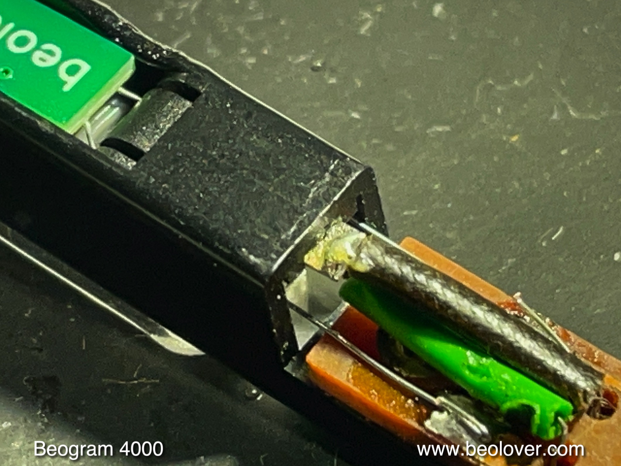
When I pulled out the sensor arm compartment it immediately became clear that someone had been 'in there' before me: One wire of the photocell was not connected, the other was mangled (from not being careful when pushing the compartment back into the aluminum profile)

and there was some heat damage to the lens insert that focuses both the light emitted towards the platter, as well as the reflected component. This heat damage likely occurred from not being careful with the soldering iron. Amateur hour! Luckily the lenses themselves were not damaged:
I was able to extract the missing wire from the aluminum tube with some narrow tweezers and reconnected it. Then I removed the non-spec light bulb that had been installed (probably disabling the arm lowering circuit due to its non-spec current draw), and I replaced it with a Beolover LED insert (see above video for more details):
Then I adjusted the bias of TR14 to yield 1.8V at the collector 
and installed the adjusted trimmer on the component side that it not interfere with the platter:
Then I measured the sensor response with the oscilloscope and got only a minuscule signal from the ribs passing underneath the sensor of maybe 100mV amplitude. Unfortunately, I forgot to take a picture of the trace. So you gotta believe!...;-). I removed the sensor compartment again, and I had a closer look at the photocell side of the compartment. Usually the photocell is o.k., but here we see that it was not in its correct position (the upside down 'U' in the top rim of the compartment opening). Instead it was hanging down at a ~45 degree angle:
This explained immediately why the signal was so low: The light was not focused on the sensor anymore. I extracted the part:
Then I took the insert to the garage and carefully Dremeled some of the melted mess to make the sensor fit again properly into the aluminum tube:
After checking the sensor by connecting a multimeter in voltage setting to the leads and measuring a promising 0.5V in front of a strong LED lamp, I decided trying installing it to see if it would still work properly. My bench test had revealed that the sensor yielded more voltage on one side than the other (0.4 vs. 0.5V), and so I installed it with the stronger side towards the lens. This resulted in a reversed polarity of the wiring that came about 'naturally' and I did at this point not understand that the polarity matters. The installation of the sensor was done by putting dabs of contact cement in the compartment and on the sensor, and after 10 min drying time carefully pressing the sensor into its slot as shown here:
After soldering the leads I tested the sensor response and I still got a 0.4V signal when shining light onto the lens compartment:
So far so good! The delicate photocell seemed to have been saved, and the need for 
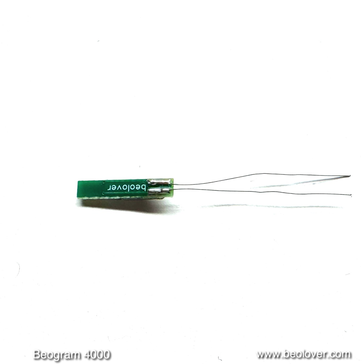
installing a modern phototransistor averted. But when I tested the sensor signal at the collector of TR14, I saw this signal, which looked inverted compared to the expected trace shape:
It immediately dawned on me that the polarity of the cell matters for this circuit and so I reversed the red and blue wire (I did not want to mess with the cell itself more than necessary)
And tried again. And now the signal looked very good:
A larger than 3V amplitude is excellent and more than enough to guarantee proper record detection. I hope I will soon play a first record on this lovely Beogram 4000!


Thursday, October 29, 2020

Beogram 4000 (type 5215): replacing sensor arm photo cell with modern one

I recently received 2 Beogram's (a BG4000 and a BG4002) on my workbench with broken photocell's in the detector arm. Normally these photocells do not wear out but the light bulbs may have their wires broken off. Beolover has already a LED replacement for these bulbs (see sensor arm light bulb replacement). However, this time the photocell had broken wires and even a broken cell.  Impossible to repair and, to the best of my knowledge, also impossible to find new ones.

Here is how the broken photocell looked like:


The photocell used in the Beogram 4000 series is in fact a photovoltaic cell (BP100). It produces energy (DC voltage) when photons from a light source hit the surface. So, it's sort of a micro solar panel! I could not find any photovoltaic cell of this size. Another sort of replacement needed to be found. 

After experimenting with photodiodes, photoresistors, ...I ended up using a phototransistor. They came out as the most sensitive and reliable components for this application. Placement inside the detector was however an issue, but luckily an "Osram opto sensor" was the perfect match. There was no need to adapt, file, cut anything. If perfectly fits snugly into the detector arm. 

                                                Dimensions are: 4,6 mm x 5,8 mm and 1,7mm thick
                                                                      type: OSRAM LPT 80A


The best way to fit the sensor into the detector unit is to first remove the light bulb, bend and isolate the wires of the new sensor and then snap it into the black detector housing. The sensor should touch the brown PCB so that the lens of the sensor is in line with the bigger lens on the detector unit.


isolate the wires with some heat shrink tubing


bend the wires to have a "drop in" into the housing and into the PCB holes


new sensor in place and soldered


light bulb back in place


Below is the new schematic with the added resistors. 


Some explanation:

The OSRAM phototransistor is an NPN type with open base. In other words, the transistor has only 2 legs (collector and emitter), the base is "open" and the incoming light triggers the transistor to start conducting. You need a power supply source off course to make the circuit working. After some experimenting, I ended up with a 22K resistor (R1) from the 6V DC available supply rail to the collector.

Since the phototransistor acts as an on/off switch, the out coming pulse is about 5V p-t-p. This is way higher than the 20 - 30mV that the original BP100 photocell was delivering. That is why a voltage divider (R2 & R3) was added so that the pulses after transistor 1TR14 where around 2,5 VDC as described in the service manual.

Note: since the new sensor is a NPN transistor, make sure the 2 wires from this sensor leading to the PCB are correct: the long leg on the phototransistor is the collector. Short one is the emittor.

Using a oscilloscoop, you can see the nice pulses generated by the phototransistor at the collector:


.....and the ones measured at the collector of 1TR14. Very close to what the service manual is indicating.


Since only 3 resistors needed to be added, I soldered them directly onto the PCB and on the connectors where the incoming wires from the detector arm are connected. To my surprise, a "spare" unused connector was installed. No idea why it is there, because it is not connected to anything. Anyhow, very convenient now....It's like the B&O engineers expected that somebody, someday, would need this 😊


These pictures are taken from the Beogram 4000. A Beogram 4002/4004/6000 will need different wiring, but the concept is exactly the same.