Featured Post

Beolover SyncDrive: DC Platter Motor Replacement for Beogram 4002 and 4004 (Type 551x and 552x)

Late Beogram 4002 and the 4004 (Types 551x and 552x), which have DC platter motors instead of the earlier synchronous AC motors usually suff...

Showing posts with label Beogram 6000. Show all posts

Thursday, December 18, 2025

Beogram 400x DIY Keypad Restoration Kit ... "How-To"

This post discusses a new keypad restoration kit that is now available through DKaudiolover, made by a partner company TangentialLab. The kit is available through the DKaudiolover store and is also used when ordering the DKaudiolover Keypad Restoration Service.


I have restored several dozen keypads over the past few years and have learned a lot in the process. Extracting the original keypad plate (without bending it) and then coating it reliably, without showing signs or wear (in the spots where the original lacquer wore through) and then it not immediately wearing out again is not really possible/reliable/repeatable (I tried!). Getting everything back to the level of quality it was originally can't really be done at the scale of "one keypad" at a time.

I have felt increasingly that given the right set of tools, and the secrets of the procedure, this could be something other restorers and enthusiasts may be able to do. The kit was put together using this experience and includes most of the items that would be difficult to source otherwise. 


Note: If you're doing this yourself, make sure you read this entire post (and the user guide) so you are very familiar with the process before you begin. Some steps involve timing and it's best to know what's coming up.

Today, I have 4 keypads that I'm working on, and I'm going to use the restoration kit for each of them.


This first step is relevant to DC model keypads only. DC (551x/552x) keypads that have "START/STOP" buttons and very sticky glue. AC (550x) keypads have "ON/OFF" buttons and generally don't need to go in the oven. The oven is required to loosen up the sticky glue B&O used on the later models. For earlier keypads, you can usually just press on the back of the keypad and it'll easily pop off the frame, as will the plastic pieces. If your AC keypad does not easily pop off, you can still use the oven method, it works for any keypad, even if it has been previously restored.

According to the guide, the first step is to place the DC keypad inside an oven-safe aluminum container to protect it from heat-cycling during the oven stage. 


Place this container inside a preheated oven at 300ºF/150ºC for about 20 minutes. After this time has passed, use heat-resistant gloves to remove it from the oven. Starting on the back side, use a large flathead screwdriver, placed between two key back pieces and rotated (to apply sideways pressure on both keys); they should break loose. Continue this process until all the backs have been removed, then put the screwdriver underneath the center piece and pry it upwards.


If you have done this quickly, there is a chance that the front side is still hot, if not then you should pop it back (in the container) in the oven for another 5-10 minutes. You don't need to keep the original plastic pieces, we will not be re-using them.

Next use the included x-acto to slide under one of the corners of the keypad plate, then slide across to the other side (front to back or vice-versa, not side-to-side yet). This will give you a gap big enough to fit a metal spatula, I suggest using a paint/spackle spatula.


Slide the spatula towards the center, make sure not to slip as you can easily scratch the frame. When you get to the inside edge of the "45" or "33" keys, you'll have to start rotating the spatula towards the front (so it's pointing towards the back). The center section is the most difficult to get across, so it's best to approach from both the left and right sides before attempting to go across. Trips back to the oven can help keep it warm if you are having trouble. Do not put too much pressure as it could suddenly break free and scratch things up. Near the end of this process, ideally you will be in this position:


Try to slowly lift "up" instead of pushing back, as it could break free and it's best to break upwards and not towards the back.

Next, for both AC and DC models, we need to deal with the old glue that is stuck to the frame. Use the included x-acto to "slide" under the glue as much as possible, try to avoid scratching the metal surface. There is a perfect angle you may find where it easily slides under. You can also "bear down" on the circle in the middle of the blade, this is the best place to put pressure.


Make sure there is no glue left over on the black painted areas, it's better to scratch the paint than to leave the glue.

It's the same process on the back side; you may even decide to start on the back side, since it's a little easier and you can practice getting the right angle and pressure.


Rinse it with warm soap and water, remove all loose glue. Use a melamine pad ("Magic Eraser") to clean the surfaces (don't put too much pressure on the visible areas of the frame as melamine can scratch or remove the lettering). Make sure it's dry before continuing.

Next, use the included paint pen to touch-up the black lines along the edge of the frame. They will have finger marks and potentially a few scratches from removing the glue.


Next, find the small bag with 4 white plastic pieces. These are alignment pieces used to make sure the keypad is centered front-to-back on the frame. They have a special type of adhesive that is "reposition able" and will not damage the frame. Remove the backings and place them at the 4 corners of the frame:


Before proceeding, test out the new keypad plate between these 4 pieces, make sure it fits and get used to centering it horizontally "by feel". I.e. you will feel when the keypad plate and frame are lined up on the sides.

Next, we'll need to remove the backing from the new keypad. It can be a little difficult to lift the corners of the backing, if you have trouble then just put a light diagonal "nick" in the corner and lift one of the side of the nick; it's the best way to remove the backing from this very strong adhesive, I don't usually attempt to get the corner lifted any other way.


The next part is critical. Don't touch the back of the plate in areas where the adhesive is now exposed. Hold the plate by the left and right edges so you can "feel" the horizontal center point with the frame. Don't push down on the keypad until you are satisfied with the centering. You can "nudge" it about 0.2mm side to side when it's lightly resting on the frame.


Note: I don't recommend re-lifting the plate to reposition it; once it's got a strong bond, it won't let go easily. If it's in a really bad spot and you can't nudge it, then just contact us so we can help.

Once you have it in a good place, press down in all the areas where the plate touches the frame.

Next, we will be preparing the black plastic pieces for adhesive. Keep the pieces "all together", do not cut them apart yet. Wipe down all the pieces to remove excess dye (there could be a lot!) and oils from the surfaces where we will be applying adhesive. Don't waste the wipe on areas that won't have adhesive, focus only on the front side.

Once the pieces are clean, wear gloves and be in a well-ventilated area. Wipe all the cleaned front sides (in the areas that will have adhesive) using the adhesive promoter. Remove gloves and wait for the promoter to dry.

Start applying the adhesive to each piece, making sure it is centered (the small pieces of adhesive are slightly larger than the key backs). Press down on the entire surface of each piece, and the edges of the small pieces (so the bond is edge-to-edge). Try to avoid air bubbles; if you get one, you can try to put a hole or two in it using a blade and carefully push the air out as much as possible.


Bend the pieces back and forth a few times to weaken the connections and cut them off (using a blade or wire cutters). Trim the sprue's so the edges are completely flat in the previous connection areas.

Note: The two upper back pieces, used for 33/45 keys, ARE DIFFERENT from the other key backs. Make sure not to mix them up! They are dimensionally unique, optimized for a tiny slope the keypad has.


Next, put a nick in the corner of each piece and peel the backing off. Below you can see where I nicked the center piece before peeling it off:


Last step is placing all the pieces into the keypad frame. Start with the center piece. Next, align each key back piece with the center of the key, about 1mm away from the center piece. You can drop the key backs in lightly and then position them with the chisel blade before pressing down too hard.


And that's it, we're finished restoring the keypad.


Actually, I did 4 of them this time:


Monday, October 24, 2022

Beogram 6000 (5505): Full Functional Restoration Pt.1

I am making good progress with the Beogram 6000 (Type 5505) from the UK. The initial assessment of this unit is posted here. This post discusses the restoration of the deck except the work on the CD-4 pre-amplifier, which will be the subject of a separate subsequent post.

This shows the Beogram as received with the panels and the platter removed:

As usual I started working on restoring the carriage. This shows the arm lowering mechanism comprised of yellow solenoid and bronze damper:
I removed all moving parts from the arm lowering section, the rods that guide the carriage, and the spindle that drives the carriage. Another part that needed to be extracted for cleaning and lubrication was the linkage that goes from damper to tonearm back. This requires the removal of the sensor arm. This shows the arm assembly taken out and the linkage removed:
Up front you can see the small copper pad that is glued to the sensor arm assembly to reduce friction between arm upper limit screw and the base of the arm. It always comes off if one tugs only slightly on it due to the degradation of the double sided tape that attaches it to the base of the arm. I usually glue it back into place with epoxy.
An inspection of the arm lowering components revealed an often found issue in this vintage Beogram 4002: A cracked solenoid arm lever extension:
This is a 'dangerous' issue, since the plastic extension has the task of activating the solenoid switch that reduces the current through the solenoid once it has lowered the arm. If it completely breaks off, the solenoid can overheat and the wire insulation of the windings burn off - usually the end of the solenoid, and it has to be rewound or replaced. I drilled out the rivets and removed the cracked plastic part. Then it was time to clean all the components in an ultrasonic bath. This shows the shiny parts after the clean:
I installed a 3D printed replacement extension on the solenoid lever
and put everything back together. Two things left to address on the carriage: The first one was to replace the original light bulb in the tracking sensor, which is situated in the black housing seen here:
I removed the bulb housing, which revealed the sensor aperture that is used to measure the arm deviation as it is pulled inward by the playing record:
After making sure that the aperture does not chafe with the sensor base, I installed the Beolover LED assembly. It has an integrated trimmer (blue) that allows adjusting the intensity of the LED light. This is very useful for fine-tuning the tracking feedback:
The final carriage task was to replace the cracked plastic pulley with a nice machined aluminum reproduction:
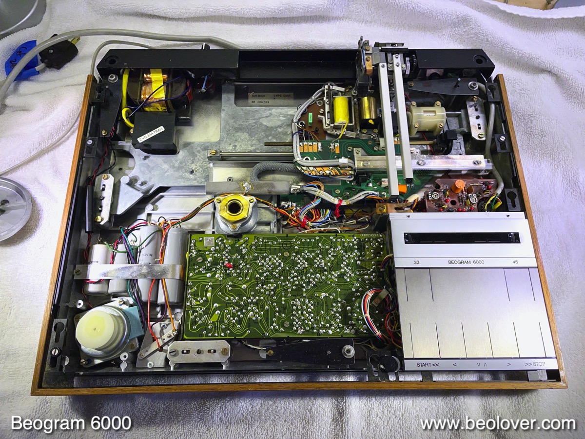
Now it was time to restore the AC platter motor and the motor and reservoir capacitor section. This shows the original setup:
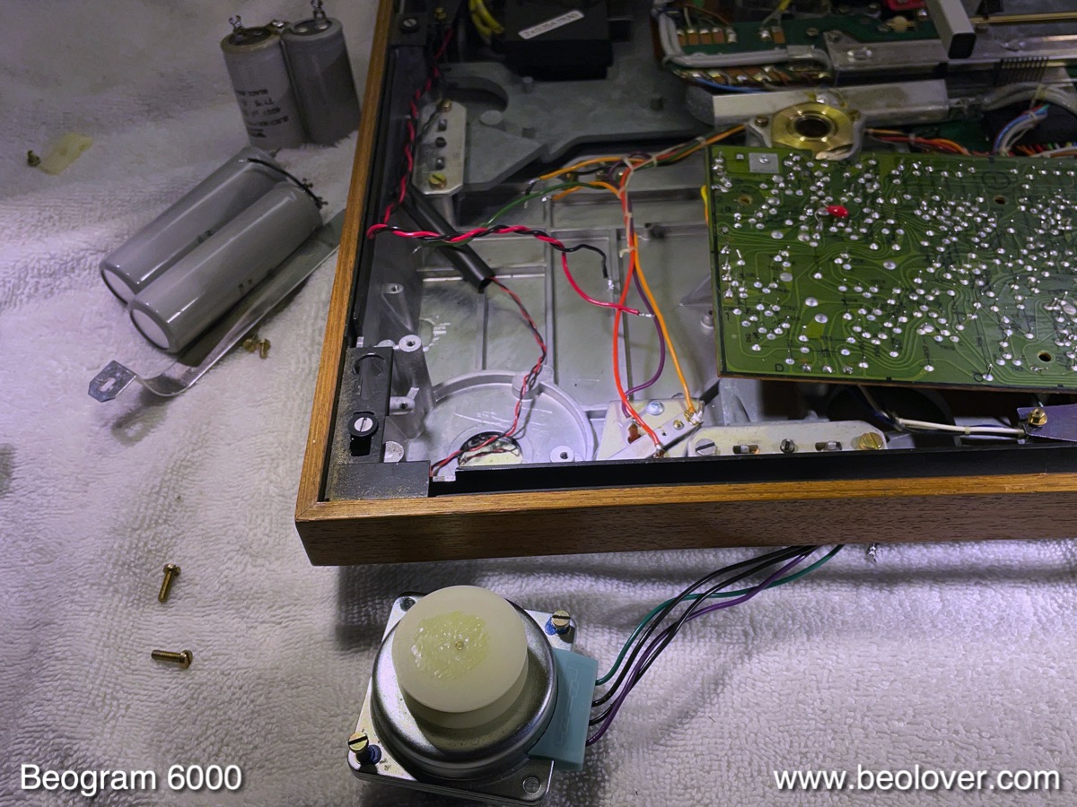
I removed all components and cleaned the compartment:

Then I was time to take the AC motor apart for an oil infusion of the bearings. This shows the motor as extracted:
And here opened up - the simple design of this brushless synchronous motor delights me every time:
I immersed the enclosure in oil and pulled a vacuum:
While the infusion was going on I had a look at the power LED wiring and found this small circuit inside a plastic tube around the wire:
It consists of a resistor and a rectifying diode, which allows to hook up the added power LED directly to the AC secondary of the transformer.
After the oil infusion I put the motor back together using 3D printed brackets to replace the rivets that I had to drill out for opening it up. then I installed it together with a 3D printed assembly that holds the new capacitors in place:
Then I lifted the main PCB up for restoration:
This reveals the two power transistors of the push-pull driver of the AC platter motor. They are bolted to the bottom of the metal enclosure for heat dissipation. Someone already had replaced the original TIP 31/32 transistors with modern TIP41/42, so I left them in place:
While the board is up it is a good moment to replace the solenoid transistor, which was still the original TIP41A:
I replaced it with a new higher voltage type, a TIP41C:
It is rated to 100V, which hopefully will help it coping better with the EMF voltages generated when releasing the solenoid. At that point I also replaced the solenoid resistor (white 'box' in back) and the electrolytic capacitor on the board (orange):
This shows the modern components implanted:
On the main PCB I replaced the electrolytic capacitors, the RPM trimmers, the sensor arm amplifier, the H-bridge transistors and the driver for the push-pull stage of the AC motor. This shows the board after replacing the parts:
After this it was time to adjust the sensor arm amplifier bias with the 25 turn trimmer that I installed to get 4V at the collector of this transistor:
Once adjusted the trimmer has to be installed on the component side to not interfere with the closely spaced platter:
At this point I focused on replacing the remaining three incandescent bulbs in the deck. This shows the RPM panel removed with bulb compartments opened up:
I usually replace the bulbs with Beolover LED assemblies that solder directly to the bulb solder terminals:
This shows them installed in-lieu of the bulbs:
I tested the LED assemblies to verify that the white background reflectors under the RPM scales do not need replacement:
At least at the 33 RPM trimmer these backgrounds are often wavy due to the fairly high heat dissipation from the original bulbs, which softens and degrades the plastic strips that form the backgrounds. In the case of this Beogram 6000, the backgrounds were in perfect condition, a further indication that this deck was only used lightly, if at all.
The final bulb to replace was in the sensor compartment at the end of the sensor arm. This shows the original setup after pulling the compartment out:
The LED replacement assembly is shown next to the bulb compartment. This picture shows it installed:
And in action:
After replacing the sensor arm light source it is always a good idea to verify that a good sensor signal is achieved when there is no record on the platter. I hooked up the oscilloscope to the collector of the sensor transistor and spun the platter by hand. This is the strong signal I was able to measure:
More than enough amplitude! While the oscilloscope was fired up, I also measured and adjusted the motor voltage. This shows the sine wave that I measured for 45 RPM:
Then it was time to do a 24 hrs RPM stability measurement with the BeoloverRPM device:
The BeoloverRPM is able to log the RPM for long periods of time. This is the curve that I measured over 24hrs:
As usual, these curves are pretty uneventful for AC motor Beograms. The AC motors run very consistently due to their brushless synchronous motor design, and the high stability of the Wien oscillator that drives them. This platter drive was ready for prime time!

The final steps before giving this deck a tryout were calibrating the tracking weight, and doing all the adjustments to parallelize the arms, platter and floating sub-chassis. The picture below shows my approach to secure the tracking weigh in place: I replace the flimsy circlip that holds the counterweight adjustment screw in place with a M3 nut:
This makes sure that the calibration remains consistent, even during transport. Then I calibrated the scale on the small weight adjustment wheel to be acceptably accurate around 1.2g, the weight that most B&O cartridges prefer:
Next was the adjustment of the arm limits. This shows the lowering limit, which needs to be adjusted that the needle misses the platter ribs at the setdown positions:
This is a safety precaution in case the arm lowering circuit would ever malfunction and lower the needle on a rotating platter without record present.
Then I adjusted the tracking sensor feedback:
At this point the functional restoration was pretty much complete, except for the CD-4 output board. I thought it would be a good idea to try and see if the CD-4 pre-amp was working at all. So I put the first record Stanley Clarke (bassist of Return to Forever) headed himself in 1974 ("Stanley Clarke", Nemperor Records NE431) on the platter and pressed START:
And, amazingly, the record sounded pretty good through the unrestored CD-4 pre-amp. A happy starting point for working on the CD-4 circuit, for sure! The restoration and exploration of the CD-4 board will be the subject of an upcoming post. Stay tuned!