While exploring an issue with the differential stop circuit of the Beogram 4000 that I recently finished restoring, I noticed another strange issue: While record detection worked at the 12" (LP) set down point, it often failed at the 7" (singles) point, i.e. when starting the deck without a record on the platter, it would pass by the LP point, but then set down at the singles point.
But let's first have a look at the circuit diagram: This shows the relevant section covering the detection system:
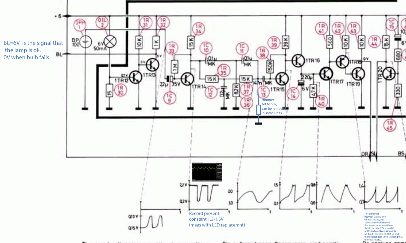
The sensor signal from BP100 on the left is fed into the base of TR14 via C9. TR14 provides an initial amplification of the weak sensor signal that then is processed further into a digital output signal for the control system. The signal is filtered in a RC network and fed through TR15,16,17,18 which essentially provide current and signal inversion resulting in a digital output signal from the collector of TR19, which is the "DR" input to the control logic in the keypad. DR is 6V if a record is present and 0V if there is no record on the platter.
So the first step of my investigation was to measure IN and OUT signals of the circuit to see if the issue is in the circuit (and not in the control logic). This is what I got:

The green trace is the amplified sensor signal at TR14. We see the usual oscillation as the ribs on the platter pass underneath the sensor. These oscillations are as specified (~0.2-2.2V), i.e. my LED replacement of the light bulb was still working fine (as expected!...;-). The yellow graph is the DR signal. We see that in the beginning as the sensor arm passes the small gap between home position and platter the signal is 6V as it should be (the gap has no ribs, i.e. it looks like a record to the detection system). Then, when the oscillations start on the green curve (sensor is now over the platter), there are a few strange oscillations in the DR signal before it settles into the prescribed 0V indicating that there indeed is no record. However, as the carriage travels further in, these oscillations start again and then even temporarily give way to a constant 6V stretch before the oscillation starts again. Absolutely not like it should be! When everything works properly the yellow signal stays solidly at 0V until the carriage returns home.
After having a bit of a think I concluded that TR19 was not providing enough current to the three logic gates that are fed with the DR signal. From the FHC131 datasheet I learned that these ancient gates take an impressive 2 mA per input when they are pulled low. So it seemed that TR19 was not fully on, causing its collector to drift towards 6V. The oscillation is probably a result of the fact that when CE goes high resistance, the BE current is concurrently reduced allowing the voltage from the (feeding) transistor TR18 to recover until the process starts anew.
After this illuminating moment I wondered about the root cause of this issue. Often one can find circuit problems by simply looking at the circuit to see anomalies like heat traces or the like. In this case my eye fell on the strange trimmer that one finds soldered to the main board on the solder side in most Beogram 4000s:

It is not on the circuit diagram. It is a 50k trimmer that connects R37/C13 to GND (I added it to the above diagram in blue). I checked the four 4000s that I have currently around, and their trimmers were all set to the maximum 50k value...somehow this suggested that whoever adjusted them seemed not to think much of them, trying to reduce their current draw as much as possible. At this point I am a bit mystified why the trimmer was added as an afterthought by the designers...there must have been some issue with the circuit under some circumstances, maybe a parts tolerance issue.
Anyway, experimentation and hunches often yield a fix and so I hooked up the oscilloscope to the collector of TR15 and measured with and without the trimmer connected. Disappointingly the curves looked very similar like this:

About what the diagram above suggested. This frustrated me a bit, but there was no stopping at this point and I marched on, connecting the oscilloscope to the collector of TR18, which feeds the base of TR19, i.e. if TR19 has trouble staying on while delivering 6 mA, there needs to be a difference in the TR18 output. And bingo, the trimmer made a big difference there. This is the signal with trimmer:

We see big spikes towards 6V, while the diagram suggests spikes no larger than 1.4V. I took the trimmer out and measured this:

Very small spikes, meaning that in this case TR19 was basically permanently on since TR18 stays fully on, i.e. TR19 should have no trouble providing 6 mA into the gates of the control system. And indeed, with the trimmer gone, the 4000 record detection mechanism started working very reliably. So the lesson learned here is to not only check the signal at TR14, but also at TR18/19 to make sure that the DR signal is stable. Alright, time to enjoy another record one this lovely Beogram 4000! Let's see if that was the last act of this eventful restoration.
**************************Note added in proof***************************************
The great Dillen of Beoworld.org sent me a message after I posted this. He indicated that this trimmer was added to the 4000 circuit as a way to adjust the sensitivity of the circuit due to the advent of transparent vinyl records. If there is a transparent record, the ribs of the platter are visible to the sensor at varying 'contrast' depending on the color and widely varying translucency of such records.
So I went ahead and experimented a bit more using a translucent red and completely clear record. This particular Beogram 4000 was able to detect both without any ambiguity with trimmer absent.
However, this does not mean that this is the case for all Beogram 4000s, since the sensor circuit is designed with analog amplification stages that are biased using a single BC resistor. This makes the gain dependent on the individual current gain value (Hfa) of each transistor, which can vary significantly, even if the transistors are from the same production run. So this issue is something to keep in mind when working on the 4000 and a verification of proper detection of clear records should be part of the 'standard restoration repertoire'. The joyful exploration of analog control systems continues!..;-)
No comments:
Post a Comment
Comments and suggestions are welcome!