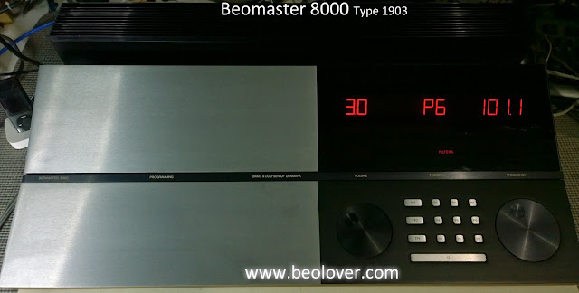
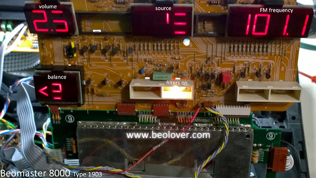
The Beomaster 8000 has very distinctive, large, red LED segmented displays that are part of its modern design Bang & Olufsen created in the early eighties. The same type of displays were used in the Beomaster 8000, Beocord 800x & 9000 cassette decks as well as the Beomaster 6000 (225x).
Here is a Beomaster 8000 with restored displays.
Here is a Beomaster 8000 with original displays already starting to fail.
Now a picture of the display components removed and a view of the front and backs together.
After disassembly of the display modules here are the various pieces.
The next photos show the details of each display (balance, volume, source selection and FM frequency). The segment identifiers are shown as well as the display component connector information (+5V or Ground) to illuminate the LEDs.
As you can see the actual LED component is not a typical, discrete LED device from that era that was soldered onto a circuit board. These LED devices were manufactured special and attached to the board by some special process. An early form of surface mounted components?
Take a close look at the original LED device on the board.
Now look at the original LED device compared to its modern surface mount LED replacement.
The SMD replacement is like a nice packaged version of the original. A perfect replacement.
The mounting of the new SMD LED devices is critical. The construction of these B&O segmented displays is such that the LED must fit right in the small slots of the plastic light guides. The bottom of the light guide piece must press flat against the surface of the circuit board to block any light from illuminating adjacent segments.
This picture shows the display components better. The top left picture shows the slots the LED must fit completely inside of.
That precise positioning spoiled a plan I had to quickly install the replacement SMD LEDs using an SMD work station. I wanted to place the whole set of LED devices on the board in some SMD solder paste then use the work station hot air gun to perform the soldering all at once. As you can imagine some of the LED devices moved off line due to the air flow from the solder gun.
The tried and true technique is to solder each LED in place by hand using a two step process. After applying generous solder flux (I use no-clean flux) to the board solder pads followed by tinning the solder pads, I gently hold the LED down with a flat metal blade as I apply a dab of solder with my soldering iron (using a very small tip). I check the position of the LED with the light guide. If it is correctly in position I solder the other side of the LED and move on to the next one. Very tedious and labor intensive for sure but it works every time.
Here is a display board with the replacement LEDs soldered in place.
Now repeat that for the other displays. For the Beomaster 8000 that is sixty-five SMD LEDs to install.
There is also some preparation of the circuit boards before installing the SMD LEDs. Some of the original LED mounting pads are a little too close together for my liking to try and fit in the new LEDs.
Here are some photos from a Beocord 9000 display restoration I did that shows what I mean about the mounting pads.
Here are the pads after the original LED devices have been cut out.
The small tabs marked in red are the pieces I want to remove.
I use a razor blade to cut the original LED device from the board trace pads. I also use the razor to cut out the small trace tab shown by the red X above. You have to be very careful and steady while doing both steps. A slip of the razor and you have a broken trace to repair. Not a good scenario. However, with the removed tab the SMD LED fits much better. Perfect really.
Here is the Beomaster 8000 volume display board after the traces have been prepared (trimmed and tinned).
And here are the SMD LEDs soldered in place.
For reference, the SMD LEDs we use are Lumex SML LX06031W-TR devices.
After the display components have been retrofitted with the new SMD LED devices they need to be tested to make sure all of the LEDs illuminate. We use a home-made test jig to perform a 24 hour burn-in test of the displays before we go to all the trouble of sealing them up and re-installing them in the Beomaster.
I use a test jig where I have duplicated the Beomaster load resistors. I use a bench power supply for 5V power and ground. Here are the displays being tested in various stages of assembly.
An optional step we do on our display restorations is to fully black-out the display component when we put everything back together. We found that by doing this we eliminate any stray light from the displays illuminating Beomaster areas that should be completely blacked out.
The sealing is necessary anyway as the original display components sealed together via a one-time-use plastic tab that was melted in place. To open the display for repair that plastic tab can only be cut off.
This display is now mechanically re-sealed and light beam sealed.
That is the whole process of restoring the display component.
Two other Bang & Olufsen audio components from this era share this LED segment display design. The Beomaster 6000 (225x) receiver and the Beocord 8000 - 8004, 9000 cassette decks.
At first look people (myself included) hoped that the displays are common and interchangeable. They are not. Here are some pictures of the displays from the various audio components side-by-side.
Even though the display segments for the display components above share the same look and number of LED segments, you can see that the mounting connectors are different and the control lines (on the rear trace side) of some of the boards are completely different. The only two that might actually be wired the same are the Beomaster 6000 and 8000 selected source display. But to try and swap those would mean a mechanical challenge of trying to get the connector leads attached properly.
The best thing to do if you have one of these components with faulty LED segments is to properly replace all of the display component LED devices with new SMD LED devices.
I hope this information is useful to other Bang & Olufsen Beomaster and Beocord owners out there.
Featured Post
Beolover SyncDrive: DC Platter Motor Replacement for Beogram 4002 and 4004 (Type 551x and 552x)
Late Beogram 4002 and the 4004 (Types 551x and 552x), which have DC platter motors instead of the earlier synchronous AC motors usually suff...
Subscribe to:
Post Comments (Atom)


No comments:
Post a Comment
Comments and suggestions are welcome!