Featured Post

Beolover SyncDrive: DC Platter Motor Replacement for Beogram 4002 and 4004 (Type 551x and 552x)

Late Beogram 4002 and the 4004 (Types 551x and 552x), which have DC platter motors instead of the earlier synchronous AC motors usually suff...

Showing posts with label switch. Show all posts

Wednesday, December 17, 2025

Beogram 4002 (5503): Arm Does Not Drop Anymore - Repair of Broken Solenoid Switch

A fully restored Beogram 4002 (Type 5503 with AC platter motor) that I sold in April 2025 to a customer in California recently had to return to the bench due to a warranty call (all Beolover-restored B&O comes with a one year warranty that covers all functional issues that may arise): After pressing ON the arm would find the LP setdown point, but it would not drop. It just sat there silently over the spinning record.

I put the unit on the bench and had a look. It quickly became clear to me that the solenoid did not get enough power to strike. Since I was able to push the solenoid lever down and it would then hold I immediately suspected the solenoid switch. This switch connects the emitter of the solenoid transistor (0TR4) to ground during the initial activation of the solenoid. When the solenoid plunger is fully extended the solenoid arm hits the switch and disconnects the emitter from ground, forcing the current to flow through the 8 Ohm solenoid resistor 4R1 (located on the PCB under the carriage). This reduces the current in the coil that it does not overheat. In this case the switch was oxidized and did not make its initial ground connection. Hence the solenoid only received the 'hold current' through the resistor and therefore did not have enough force to overcome the force of the release spring and friction etc...

This picture shows the small PCB that sits to the left of the solenoid, which holds this switch:

The switch is under the wiring. After unsoldering the three wires that connect the board and removing/loosening the two screws it can be removed:
I replaced the switch with a new one:

It is generally not a good idea to just sand the contacts a bit when this switch fails. While it can restore function for a while it usually does not last. The reason for the switch failure is that the oxidation preventing coating of the contacts burns off after a sufficient number of activations due to arcing. Therefore, the contacts quickly re-oxidize when they are sanded and it fails again. This switch carries about 3-4 amps during solenoid activation and breaking this current can cause small arcs. This is probably the reason why B&O replaced this switch with a timed electronic current limiter in the later DC motor 4002s and the 4004.

After reinstalling the board everything worked normally again. I played a couple records without a hitch, i.e. this Beogram 4002 is ready to return to its owner.


Thursday, January 23, 2025

New Beolover Carriage Position PCB for DC-Motor Beogram 4002/4004s (Types 551x and 552x)

I always found the repair and adjustment of the carriage position sensor on the PCB underneath the carriage somewhat tedious. The board and circuit are designed in a way that make a precise alignment of the LED, sensor and plexiglass ruler across the entire travel of the carriage necessary to ensure proper functioning. At the same time photosensor failures and mechanical failures of the sensor housing or the two switches on this board were sometimes difficult to fix, while broken off wires occasionally caused operational issues.

So I decided designing an improved board that would provide a reliable fix for all these issues at least in DC-motor Beogram 4002/4004s (Types 551x and 552x), where this board can be easily replaced. This shows the final design of the board:

The board features new SO and ES switches, as well as a modern monolithic IR photo-interrupter whose signal is cleaned up and shaped by an opamp in combination with a Schmitt trigger. It connects with a modern harness using a 2.54mm 8pin adapter to match the classic Molex jack on the main PCB. This connection should last much better than the original soldered wires.

The part is now available at the Beolover Store. I also gave this board a built in sensor test feature. Flip the switch to the right and an integrated LED will light up every time a black band on the ruler is properly identified by the sensor:

This shows the board installed:

My tests yielded a proper carriage position detection, while the SO and ES switch were in the correct location and performed perfectly. It seems that the modern photo interrupter due to its fixed alignment between LED and phototransistor is much more forgiving regarding the distance between ruler and photosensor. This makes the alignment between ruler and sensor across the entire translation range of the carriage much easier.
A good test for the proper functioning of the position sensor is whether it can read out the run out groove detection pattern at the end of the ruler. I measured the signal at the collector of TR17 while this section passed through the sensor:
A nice clean trace! All good in the carriage position detection department!


Thursday, September 7, 2023

Beogram 4002 (5503): When Disaster Strikes! - Replacement of the Solenoid Switch and Restoration of a Melted Solenoid

Oh well! I recently received a Beogram 4002 (Type 5503) from a customer in Arizona with the indication that 'it does not lower the arm anymore'. I had restored the unit only in Dec. 2022, so this was a bit early for my taste to see it again!

After I removed the aluminum panels it became immediately clear why the arm would not lower again!:

The solenoid had completely melted down! I measured its resistance and it was about 1.2 Ohms. Normally it should have about 9 Ohms. Why this happened also became clear quickly. My solenoid arm extension part did not hold up. It cracked in a very similar way like the original arm extensions:
Because of this weakened arm link the solenoid switch did not get activated anymore and so the solenoid ran at full power even after the arm had been lowered. At some point the insulation of the coil wiring burned off, short circuiting the coil and that was the end of the arm lowering function. 
I extracted the solenoid
and took it apart:
Then I made a new coil. Luckily I recently learned how to do that:
This shows the new solenoid installed in the original bracket:
After I implanted the solenoid I had to realize that it would not activate at full power. This turned my attention to the solenoid switch. I found it to have a too high resistance when closed. And that caused the solenoid to be underpowered. Maybe the switch-terminals also suffered during the solenoid burnout. But it also did not click properly when activating it manually, so there was something wrong with its mechanics, too.
Since these switches are not made anymore, I had to figure out a 'modern replacement'. Immediately, I thought about the end switches used in 3D printers. They have a suitably small form factor, but they usually are only rated for switching DC currents up to an amp or so. Not enough for handling the typical 3-4 Amp current in the Beogram solenoid when it is activating. 
After a bit of thought I decided to try using a power transistor for the 'heavy lifting', and the switch only for activating the transistor. This approach promised reducing the mechanically switched current by about 2 magnitudes since the current gain of such transistors is typically in the 100x range. In other words the switched current promised to only be in the sub-100mA range. 
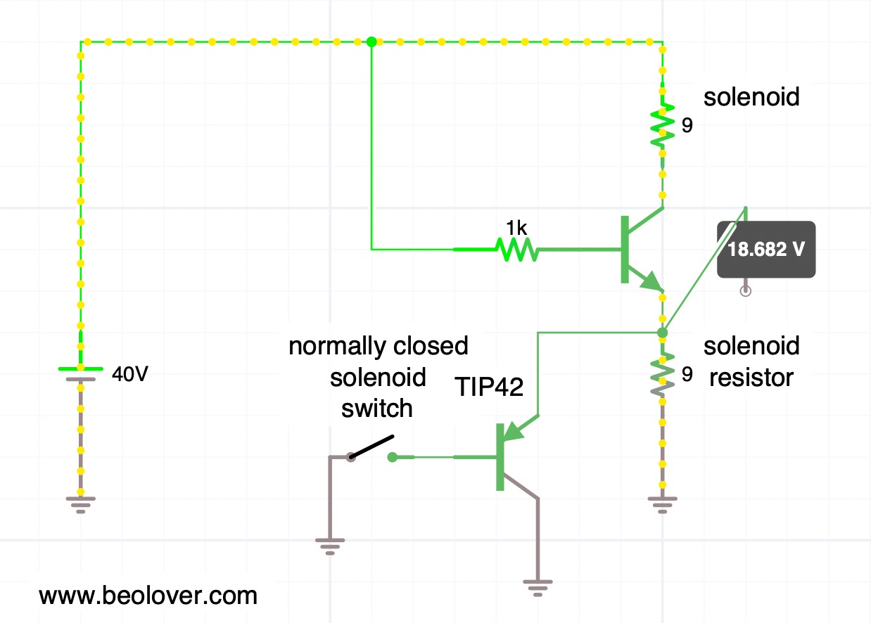
This is the simple circuit that I implemented using a end switch connected as a normally closed switch, so the TIP42 pnp transistor would be on when the solenoid is initially fired up to sink the solenoid directly into ground. This is the situation shown here (yellow beads show the main current flow):
You see that the simulation shows a voltage of about 0.7V at the emitter of the solenoid transistor. This means that the solenoid sees almost 40V driving it with about 4.3 amps based on its approximate 9 Ohms resistance.
After the solenoid activates and pushes its plunger out the solenoid switch gets hit and the TIP42 turns off, sending the current solely though the solenoid resistor. This causes the voltage across the solenoid to be dramatically lowered and with that the current gets reduced:

This situation is maintained during the play of a record when the arm is down.
This shows this concept put into practice on the solenoid switch PCB that I extracted to be able to work on it:
I found the best switch position by trial and error, and then drilled a hole into the circuit board so I could anchor it with a 2mm bolt in place. The TIP42C is bolted in via one of the two mounting screws of the PCB. The way it is connected still allows the board to be be shifted up and down to fine tune the switch position. This is important to make sure the arm hits the switch in a way that it really switches.
The last task was the re-design of my solenoid arm extension. I got rid of the nut and instead used a self-tapping 2mm screw that would put only minimal stress on the plastic. I added a liberal amount of epoxy in the bolt hole and the compartment that receives the end of the metal arm to keep things from separating. This shows the result:
Let's hope this holds up better!
Here you can see the arm in concert with the switch. First with the solenoid off:

And now with the solenoid activated:
Once the solenoid demonstrated to actuate properly, I measured the voltage across it during the activation process. In this measurement the trace corresponds to the signal measured at the collector of the solenoid transistor (0TR4).
But first I measured a reference signal that I was able to obtain conveniently from another 5503 that I have on the bench currently:
Before activation of the solenoid, the voltage at the collector is essentially the same as the power rail, i.e. ~40V. This means the solenoid has 0V across it. Once the solenoid transistor activates, the voltage across the solenoid increases to about 40V and then, after about 10ms, the solenoid arm hits the switch, and the solenoid gets disconnected from ground, and the current flows through the solenoid resistor instead. This results in a strong voltage reduction across the solenoid and it has now only about 8-10V applied to it. This real-life voltage is less compared to the simulation above. I think it comes from the fact that in the simulation I drive the solenoid transistor with an arbitrary 1k resistor connected to 40V, while in the real circuit a series of transistors (TR14/15/16) drives it with a different current.
What really counts is: Does the TIP42 replacement result in a similar behavior as with the original switch? Happily it does as is evident from this trace that I measured on the implemented circuit:
This trace is hardly distinguishable from the standard circuit behavior and so we can conclude that this may be a good fix for broken solenoid switches!
All good again in the arm lowering department of this Beogram 4002! Beolove is sometimes a bit painful, but only steady improvement leads to perfection. And that is what the Beolover aims to achieve!


Friday, September 25, 2020

Beogram 4002 (5503): Unit Switches Immediately to 45 RPM After Pressing Start

The Beogram 4002 (5503) that I am currently restoring exhibited a strange phenomenon when I tested it the first time after rebuilding all its functional parts (more about this process in a subsequent post):

After pressing START the carriage began to move while it immediately switched to 45 RPM. Pressing the 33 key switched it back to 33 RPM, but only as long as the key was pressed.

This immediately suggested that either TR3 or TR2 had an issue. Let's have a look at the relevant section of the circuit diagram:


This is how the speed selection works:
The base of TR3 is connected to the collector of TR4, and the base of TR4 is connected to the collector of TR3. Resistors 5R1 and 5R2 act as pull-up resistors together with the light bulbs IL1/2. I guess the resistors were added to keep the deck working even if a bulb burned out.
This causes a flip-flop behavior: When the base of TR3 is shorted to ground via the 45 switch in the keypad or TR2 (that is activated by the carriage as it travels towards the set-down point for singles), TR3 is turned off for a moment, causing its collector to go high, which in turn pulls the base of TR4 up, and that drives the collector of TR4 to GND since TR4 turns on. This then keeps the base of TR3 permanently grounded and the deck is running at 45 RPM (via switching TR6 on which changes the oscillation frequency of the Wien Oscillator to drive the AC motor at a higher RPM).
The opposite happens when the 33 key is pressed. This causes TR4 to be off and TR3 on, and so TR5 is turned on running the oscillator at a lower frequency.

I removed TR3 and checked it with my transistor tester:

Apparently it had turned into a voltage divider!...;-).
I replaced TR3 with a generic BC547B and that fixed the issue.

Thursday, May 24, 2018

Beogram 4004 (5526): Installation of A New Output Cable

After replacing the light bulb in the sensor arm with an LED assembly it was time to look into the RCA plug 'conversion' of this Beogram 4004 (5526). This shows the output cable in the condition when I received this Beogram:
Not a very inspiring sight. The blue and yellow leads are the Beolink signal lines that allow controlling the 4004 via a Beomaster 2400. We decided to return this 4004 to its original DIN7 output scheme. Originally the 4004 came with a convertible male DIN7 plug, which can be turned into a standard DIN5 by unscrewing the two pins that are extra in the DIN7 format. This shows a plug as seen on a 4004 I restored a few years ago:
The two outer pins were removed so that the plug essentially acted like a standard DIN5 phono output. Unfortunately, such DIN7 plugs are not available anymore. A solution I came up with is to install female DIN7 plug that has all the signals on it. If extended with a DIN7 cable it turns into a DIN7 male output that will properly work with a Beomaster 2400. Extend it with a DIN5 or a DIN5-to-RCA adapter and a standard non-B&O phono output is achieved.
This shows the female DIN7 plug during the installation:
Note that the leads need to be soldered in a mirrored pattern compared to that applied for a male DIN7 plug, since male-male DIN5 and DIN5-RCA jumper cables mirror the leads for symmetry reasons.

This shows the DIN7 connected to a DIN5-to-RCA jumper cable:
The system ground connection is on a separate wire (not visible on this photo) that it can be connected to the GND terminal of the RCA input amplifier.


Thursday, April 5, 2018

Beogram 4000: An Entertaining Evening Exploring the Differential Stop Circuit

Before we send a restored unit back to a customer, we always give them a good 'real world' test, where we simply play a bunch of lovely music over a couple weeks and observe if everything works consistently. The listening part is of course part of the fun of Beoloving! There is always music in the work shop! The case of a recently restored Beogram 4000 is a proof in point of the usefulness of such testing phases: While playing a number of records, I noticed that occasionally the arm would not return to the home position once the end groove had been reached. Normally, the Beogram 4000 detects the end groove spiral due to the higher speed of the carriage and then lifts the arm and returns the carriage. Not in this case, though, where the needle simply went all the way in and then kept playing the final turn over and over again...tock...tock...tock...not very Beolovely!

The problem was that this would only happen occasionally, but most times everything would be fine. Such problems are hard to troubleshoot. In the beginning I thought it was simply a MV switch issue (most 4000 issues come from not working switches), but since I had coated the switch terminals with gold, tests demonstrated that the switch was working very reliably. So I concluded the problem must be in the differential stop circuit, which produces the logic DS level that tells the control system that it is time to lift the arm and return the carriage home. This shows the relevant part of the Beogram 4000 circuit:


This is how it works: The detection of the end groove is done via the carriage motor voltage. Since the end groove typically makes the carriage move faster, the motor voltage is larger than during normal play back of a track. That is why the circuit is called Differential Stop (DS), the end groove is not determined by the position of the arm, but by its velocity towards the center of the record. One of the issues is that the arms do not only move faster in the end groove, but also between tracks and in the run in groove at the outer rim of the record. This problem is solved by introducing a carriage activated switch ("MV") that enables the DS circuit only close to the end groove region of the record. This switch is on the second circuit diagram of the 4000 and it connects MV and MV' in the above circuit snippet.
So when the carriage reaches a point about 65mm away from the center of the record MV and MV' are connected. This causes the voltage that is applied across the motor to be applied across base and emitter of TR24 via 1R54 and trimmer 1VR4. The trimmer is used to adjust the carriage speed threshold at which TR24 turns on (this adjustment turned out to be the critical item during this exploration...read on...;-). When TR24 turns on due to high carriage speed, it then turns on TR23 which serves as an additional input that allows other functions of the turntable to disable the DS circuit (mainly system requested and manual FF function via TR25). When TR23 turns on TR22 becomes conductive and grounds its collector. This causes the logic signal DS to go to 0V. DS then activates carriage return via the logic ICs in the control panel. This immediately turns off the DS circuit since the motor voltage reverses (the MV switch remains closed until the carriage clears the switch on the way back to home position). The result is an about 5-10ms pulse at DS as is shown in this oscilloscope snap shot:
The blue trace is the DS signal. Green and yellow are the (motor) voltage measured on both ends of the MV switch against GND (since it is closed at this moment both traces are the same).
We see that when the motor voltage changes due to the reversal of the carriage direction the pulse terminates.

Ok after this circuit discussion...back to the 'issue' that I was trying to solve, the occasional not working of the DS mechanism:
After I verified that the MV switch worked reliably, I thought the issue must be an intermittent problem with the DS circuit. Since the issue was very intermittent, I used an Arduino as event recorder:
I used one of the pin change interrupts to detect the state of DS and print it out on the serial port whenever it would change from 6V to 0V, i.e. when the circuit activated DS. Then I played some records and waited for the issue to happen. Luckily the second record I played triggered the issue. And, guess what, DS indeed did not change. This told me that the issue is in the circuit. I played another record, and it worked again. Then I put on the previous record and it happened again! This finally turned on some light bulbs in my head. I put the other record on and it worked again! The light became very bright in my head and I concluded: It is the record, dummy! The circuit was basically working, but the records are different! This shows the end grooves of the two records in comparison: First the one that made DS work properly:
and the one that caused DS to fail:
What is the difference? The number of turns the end groove takes until it hits the innermost groove. This means that the first record makes the carriage move faster than the second does. The consequence is that the motor voltage is lower when the arm reaches the end groove of the second record. This shows an oscilloscope trace of the motor voltage (measured by connecting the oscilloscope trace to one motor pin, and the oscilloscope GND to the other) as the needle goes from track to end groove:
The waves on the left are the normal voltage fluctuations on the motor as a track is played. Then as the end groove begins the voltage goes down and then the shoots up as the voltage across the motor is large enough to trigger TR24. So it appears that the non-triggering record simply did not cause the voltage to cross the threshold. I ended up adjusting the VR4 trimmer a bit clockwise and then the mechanism worked also for the second record, yet still played the last track to the end (a good test for that is playing a single, since their single track usually extends into 'MV switch closed territory'). So in the end, nothing was wrong, just the adjustment needed to be changed a bit towards more sensitivity. 
An interesting thing to note is that the service manual prescribes to adjust the sensitivity that DS gets triggered at 1.8V motor voltage. This is obviously too sensitive since the amplitude of the waves in the oscilloscope trace above is about 2.2V. If the threshold were adjusted to 1.8V DS would be triggered during normal playback and not only in the end groove. The joys of analog control systems!


Saturday, March 17, 2018

Beogram 4000: Upgrade of Signal Path with New DIN5 Plug and a Grounding Switch

As usual the original DIN5 plug on the Beogram 4000 that I am currently restoring was badly oxidized. This shows the original plug:
I replaced it with a new all-metal plug that has gold coated terminals:
Another useful upgrade of the signal output of any Beogram is the installation of a switch that allows connecting signal and system grounds. This is a useful feature if the Beogram is ever to be used with a DIN5 to RCA adapter. Since RCA cables do not carry the system ground, connecting it to the signal ground on the Beogram often eliminates humming. This shows the output terminal assembly of the Beogram 4000 in its original condition:
This open layout makes it very convenient to add a switch:
The shown switch position connects the two ground. Flipping the switch would open the connection.


Monday, March 5, 2018

Beogram 4000: Restoring the Carriage Position and Solenoid Driven Switches

After rebuilding the keypad cluster of this Beogram 4000 it was time to see to the remaining mechanical switches that control the Beogram's performance. There are two clusters, one beneath the carriage where the switches determine the position of the tonearm, and the other next to the solenoid. The solenoid activated switches are responsible for the activating the tracking mechanism, opening the outputs when the needle is in the groove and to regulate the solenoid power down once the arm is lowered.
This shows the carriage position switches. For getting to them it is best to drive the carriage inwards and remove the red position indicator assembly. Then the board is fully accessible:
After unsoldering the two leads that power the carriage motor and removal of two screws the board can be pulled up and turned around:
Some oxidation is visible on the back of the terminal tabs. For some reason the carriage position switch terminals are usually less oxidized than the other switches under the keypad and next to the solenoid. I removed the terminals
and coated them with gold:
Then it was time to solder them back in and clean the plastic plungers that activate the switches from 40 year old hardened grease. Then I turned my attention to the switches next to the solenoid. The single switch assembly that controls the solenoid power can be directly accessed after removing the two screws that hold it in place:
I extracted the terminal and then removed the assembly that holds the output and tracking activation switches:
This assembly needs to be taken apart while not ripping the thin wires off that are connecting the switches to the control system:
Once this was done I extracted the three terminals. This shows all four terminals as extracted:
'Beautifully' oxidized, I'd say! I brushed the oxide off with 2000 grit paper and a fiber glass brush and then coated them with gold:
That looked much better! I put everything back together and gave the system a first test...Good news: so far everything seems to work...the carriage is now setting down the arm at the 12 inch point and the solenoid actuated properly. A significant milestone has been reached in this restoration!


Friday, February 23, 2018

Beogram 4000: Restoration of the Keypad Cluster

After replacing the electrolytic capacitors and restoring the AC motor of the Beogram 4000 that I am currently restoring, it was time to rebuild the keypad cluster. The PCBs below the keypad house the control center of the Beogram, which is a unique early digital control system based on TTL logic chips. This logic system comes to its operational conclusions largely based on inputs caused by the many mechanical switches throughout the turntable. The keypad contains 8 of them enabling user interaction with the Beogram.
The keypad is held in place by a single screw, which was missing in this Beogram:
An indication that 'human interaction' had taken place earlier (which was confirmed once I looked at the switches on the PCBs - see below). I took the pad out and opened it up:
The upper board contains some of the logic chips and the light bulbs that illuminate the position indicator and the RPM trimmers. The lower PCB is populated with the eight switches for the keypad and one more logic IC. As usual, the switch terminals were heavily corroded:
I removed the board from the keypad, which is necessary for extracting the switch terminals:
This shows the side of the board that houses the switch actuators. The small green, white and grey 'plungers' are actuated by the keys on the keypad, which pushes the switch terminals on the other side of the board making or breaking the associated contact. Note the location of the single grey plunger top left. This is the wrong location for this particular one. It needs to be in the center of the bottom row, since this particular switch is a break switch. This incorrect installation immediately explained the malfunction of the arm lowering circuit that I noticed after the restoration of the main PCB. The green plungers are longer, and therefore this switch, which is responsible for lowering the arm, was permanently open (actuated). This shows the three switch types in comparison:
The grey one is the shortest. It is used for break switches. The green one is used for make switches and the white one is for two-pole make/break switches (the << and >> keys, which have slow and fast functionality, depending on how hard the keys are pressed).
I removed the switch terminals:
After removal of the oxide layer with 2000 grit sand paper, I coated the terminals with a gold layer:
and then soldered them back into place:
The final step was to replace the light bulbs with LEDs. The position indicator scale lights were replaced with custom designed LED boards (available to other B&O enthusiasts), each containing two red-green LEDs tuned to yield an incandescent-like sheen. The RPM trimmer back light bulbs were replaced with standard red LEDs and current limiting resistors:
This shows the LEDs in action after installation:
After that it was time to put the keypad back together. Unfortunately, the center key was not attached to the keypad, i.e. I needed to reinsert it. This can be difficult and there is a danger to scratch the other keys while doing it. For this reason I used 3D printed tools that I developed earlier, which make this process much easier. They allow pre-bending of the spring that holds the pad in place and that allows it to bounce back after pressing it:
Once the spring is bent up, it is fairly easy to get the pad on it. Careful removal of the printed taps releases the spring holding the key in place. And this shows the pad installed:
A test revealed that all keys are now working properly. On to gold coating the remaining switches below the carriage and in the arm lowering mechanism.