Featured Post

Beolover SyncDrive: DC Platter Motor Replacement for Beogram 4002 and 4004 (Type 551x and 552x)

Late Beogram 4002 and the 4004 (Types 551x and 552x), which have DC platter motors instead of the earlier synchronous AC motors usually suff...

Showing posts with label oxidation. Show all posts

Thursday, June 28, 2018

Beogram 4002 (5513): Keypad and RPM Panel

I noticed that some of the Beogram's control panel buttons were slow to respond when pressing them. That usually means oxidation on the keypad contacts so I opened up the keypad assembly.
Sure enough, you can see the dull key contacts.


I unsoldered the contact pads and removed them for inspection. They didn't look too bad but the leaf contacts that the actuators press down on are all oxidized.


I used a fiberglass brush and some Deoxit to protect from future oxidation. The contacts all look nice and shiny again.


The last part of the electrical work is to change out the lamps for the RPM indicators. We recommend this because during the platter motor stability testing the LED replacement modules resulted in further stability of the motor speed. The RPM indicator lamps are part of the circuit that controls the platter motor. Each speed indicator has a knob to adjust the pitch (speed).

Here is the RPM indicator module with the original incandescent lamps.


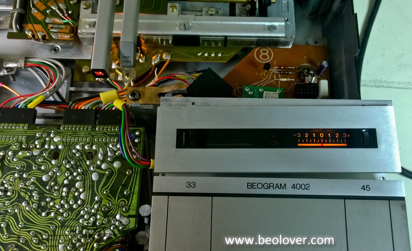
Here is the RPM indicator with the Beolover lamp replacement modules.


The Beolover lamp replacement module is designed to work with the pitch control circuit and the SMD LED components used have been adjusted to mix light colors to match the original incandescent lamps.

Here are the 33 and 45 RPM speeds with the new light modules. The control panel buttons operate immediately as they are pressed now.


All of the Beogram functions are operating now. The next step is to check and adjust the Beogram per the service manual. Once those adjustments are made and all the checks pass it will be time to play vinyl again.

Monday, March 5, 2018

Beogram 4000: Restoring the Carriage Position and Solenoid Driven Switches

After rebuilding the keypad cluster of this Beogram 4000 it was time to see to the remaining mechanical switches that control the Beogram's performance. There are two clusters, one beneath the carriage where the switches determine the position of the tonearm, and the other next to the solenoid. The solenoid activated switches are responsible for the activating the tracking mechanism, opening the outputs when the needle is in the groove and to regulate the solenoid power down once the arm is lowered.
This shows the carriage position switches. For getting to them it is best to drive the carriage inwards and remove the red position indicator assembly. Then the board is fully accessible:
After unsoldering the two leads that power the carriage motor and removal of two screws the board can be pulled up and turned around:
Some oxidation is visible on the back of the terminal tabs. For some reason the carriage position switch terminals are usually less oxidized than the other switches under the keypad and next to the solenoid. I removed the terminals
and coated them with gold:
Then it was time to solder them back in and clean the plastic plungers that activate the switches from 40 year old hardened grease. Then I turned my attention to the switches next to the solenoid. The single switch assembly that controls the solenoid power can be directly accessed after removing the two screws that hold it in place:
I extracted the terminal and then removed the assembly that holds the output and tracking activation switches:
This assembly needs to be taken apart while not ripping the thin wires off that are connecting the switches to the control system:
Once this was done I extracted the three terminals. This shows all four terminals as extracted:
'Beautifully' oxidized, I'd say! I brushed the oxide off with 2000 grit paper and a fiber glass brush and then coated them with gold:
That looked much better! I put everything back together and gave the system a first test...Good news: so far everything seems to work...the carriage is now setting down the arm at the 12 inch point and the solenoid actuated properly. A significant milestone has been reached in this restoration!


Saturday, June 3, 2017

Beogram 4000: Gold Coating of Solenoid Activated Switch Terminals

The third group of switches that control the Beogram 4000 is comprised of four switches that are activated by the solenoid when the tone arm is lowered. Like the other switches in keypad and under the carriage these usually suffer from oxidation. One of the switches is particularly important, since it controls the solenoid current during lowering activation. If it is oxidized, the arm will not lower anymore. Therefore, we strongly recommend to also get these switches gold plated like the others. This shows the switch assembly next to the solenoid (this photo shows already the gold plated terminals - I forgot to take a picture of the original condition):
The switches are installed on the three small vertical PCBs that are soldered to horizontal base-PCBs. The left most switch activates the tracking system once the arm is down. The two switches on the center PCB are the output switches that ground the cartridge signal lines while the arm is up, and the right most switch (under the wide yellow conduit) reduces the solenoid current to a lower value once the arm has been lowered.

These switches are a bit more difficult to get to than the others since they are connected to many flimsy wires. The solenoid current switch terminal is the only one that can be removed directly after unbolting its base-PCB:
The other two vertical PCBs need to be removed from their base-PCB to access the switch terminals. The first step is to unbolt the base-PCB and turn the board around that the solder points for the vertical boards can be accessed:
Unsoldering requires three hands, but with a de-solder pump and a bit of persistence it can be done with only two...;-):
After removing the oxidized and deformed terminals
I electroplated them:
And then it was time to put them back in:
Nice! On to the PCBs!


Friday, June 2, 2017

Beogram 4000: Gold Plating of Carriage Position Switch Terminals

After restoring the command center (aka 'keypad'...;-) of this Beogram 4000, it was time to restore the carriage position switches. Their functioning is crucial for the Beogram 4000's digital control center and the malfunction of just one of these switches will make it impossible to use the Beogram. Like the keypad switches, they are susceptible to oxidation and gold coating is a reliable remedy for potential contact troubles down the road. This shows the PCB that features the switches after removal of the carriage position indicator assembly:
After removal of the servo motor leads and the two screws that hold it in place, the board can be flipped up:
While the contact tabs look shiny and happy on first glance, their removal reveals oxidation in the contact areas (small black dots):
Electrochemical processes enabled by the humidity in the air acting as electrolyte the terminal metal oxidizes where it is in contact with the opposing contact terminal. Coating with a noble metal like gold is a good idea since it dramatically slows down this process. This shows the terminals after the electroplating process:
And after installation:
All good in the carriage position switches department! On to rebuilding the main PCB and the reservoir and motor capacitors!


Thursday, June 1, 2017

Beogram 4000: Restoration of the Keypad Assembly - Gold Plated Switch Terminals and Light Bulbs Replaced with LEDs

After restoring the arm lowering and tracking mechanisms, it was time to rebuild the command center of this Beogram 4000. The keypad assembly contains an early digital control system, which responds to inputs by the keys on the keypad. The mechanical switches associated with the keys are one of the most often malfunctioning features of this design. This is why we recommend to gold plate the terminals in these switches to ensure trouble-free long term performance after the restoration process.
This shows the keypad cluster extracted from the Beogram and opened up:
One immediately sees that one of the light bulbs of the position indicator scale is missing. The other, still present one was not working, too. The chips that are visible are early TTL gates that comprise the digital control system that orchestrates the functions of the Beogram. The keypad switches are located in the lower PCB:
The black spots are oxidation, which often renders these switches permanently open circuit. A quick fix is to pull some 2000 grit sand paper through the terminals and their counter electrodes. But this is only temporary since the oxidation quickly grows back. It is better to remove the terminals, clean them and then electroplate them with a layer of gold. This shows the terminals removed in their original condition:
And after the plating process:
After soldering them back in the OFF button started to work again. After restoring the switches I replaced the light bulbs with LEDs. For the position scale illumination I use red/green LED-based assemblies that are tuned to emit an incandescent-looking spectrum which contains also red. This is important since the position indicator is a red piece of plastic, which would not appear red without the presence of red photons in the LED light. This is the reason I do not use amber LEDs for such tasks. The position indicator would look grayish in the light of amber LEDs. This shows the LED boards:
The RPM indicator bulbs can be replaced with standard red LEDs and current limiting resistors (the bulbs run on 12 V):
This shows the LEDs installed and in action:
And this is how the LED keypad illumination appears when looking at the keypad:
Beolovely! On to the carriage position indicator switches (you guessed it! they also need to be gold plated...;-)!


Friday, January 20, 2017

Beogram 4000: Restoration of the Control Panel - LEDs and Gold Plating of Switch Terminals

After gold plating the carriage position switches, it was time to rebuild the control panel of the Beogram 4000 that I am restoring right now. I usually replace the incandescent light bulbs with LED assemblies, and I gold-plate the switch terminals to ensure trouble-free operation down the road.
This shows the original keypad switch terminals, which were quite oxidized:


I removed the terminals:
And gold coated them after removing the oxidation with a fiber glass pen:
And like with the last Beogram 4000 that I did, I forgot to remove one terminal in my first approach...not funny! Here we go:
and after coating:
Pretty, aren't they?? Then I soldered them back into the PCB:
The next step was to replace the light bulbs with LEDs. This shows them in action:
The position scale illumination bulbs were replaced with my custom designed dual red/green LED assemblies:
These boards are available to other enthusiasts. Just send me an email if you want to upgrade your Beogram 4000!
The bulbs that illuminate the RPM trimmers from the back were replaced with through hole high brightness LEDs that are dimmed with 3.3k resistors:
Using strongly dimmed high brightness LEDs saves more current further reducing the strain on the transformer of the Beogram (which gets pretty warm during play) along with the other LEDs that I implanted.
This is an impression of the LEDs in action:
The red-green LEDs create a very authentic background illumination for the position indicator while the presence of red photons in the LED light ensures that the indicator shows up red like when illuminated with incandescent bulbs.


Monday, January 16, 2017

Beogram 4000: Gold-Plating of the Carriage Position Switch Terminals

The next step of my Beogram 4000 restoration was to electroplate the carriage position switch terminals with gold. In my experience 90% of all operational trouble with this B&O design comes from oxidized switch terminals. These switches present the digital control system with the necessary inputs about the carriage status and if they malfunction, the control system gets thoroughly confused. So my recommendation is gold-plating of the switch terminals. Gold does not oxidize easily and therefore this will result in significant long-term reliability improvements. This shows the carriage switches as I found them:
Not too bad compared to what I found before in other Beogram 4000s, but definitely some black spots indicating oxidation. I removed the terminals:
The oxidized contact points are clearly visible. I cleaned and gold plated them:
And soldered them back into the circuit board:
the next step is to do the same for the switches in the keypad.