Featured Post

Beolover SyncDrive: DC Platter Motor Replacement for Beogram 4002 and 4004 (Type 551x and 552x)

Late Beogram 4002 and the 4004 (Types 551x and 552x), which have DC platter motors instead of the earlier synchronous AC motors usually suff...

Showing posts with label 177AABG4000. Show all posts

Friday, April 28, 2017

Beogram 4000: Repair of a Cracked Plexiglass Hood With Laser Cut Patches

The most fragile part of a plexiglass hood of any Beogram is the hinge region. That is where the highest torque is applied to the plexiglass, while it is structurally weakest due to the holes permitting the screws that hold the metal hinge to the hood. The Beogram 4000 that I recently restored had a hood with a large crack through the holes and a broken out piece:
Encouraged by my recent restoration effort on a Beogram 3000 hinge that was broken off I decided to develop a similar fix for the 4000/4002 hoods. Unfortunately, the space one can work with is much less in 400x hoods, since the metal hinge part is bolted to the inside of the hood, i.e. if the plexiglass gets too thick, the metal part does not fit anymore. So my approach here is to use two very thin 20 mil (~0.5 mm) patches that are precision matched to the bolt holes and the hood shape.
But the first step is to try to glue the cracked parts and re-connect the broken out part:
I use Weld-On #4 acrylic glue, which is so liquid that is is drawn into cracks by capillary forces. This is a great feature since one does not have to bend the plexiglass any further to apply it. All one does is squirt a bit on the crack and one can see how it is sucked in. One can then simply press the parts a bit together for ~5 min (play some nice music while you sit there holding the pieces together...;-) and then the next step can be done, which in this case was reattaching the broken out part:
Another 5 min of music listening and then I let it cure for a couple hours. The next step was to attach the laser cut patches. This shows the inner patch:
I used Weld-On #16 for these, since the surface was pretty rough due to the broken out part and previous 'repair' attempts. After curing the patch for ~2 hours (=50% strength of the bond) I did the same for the outer patch:
At this point I let everything cure for 24 hrs to achieve a close to final strength of the bond (~80%). Only after a few days such bonds are fully cured and 100% strength is achieved.
In order to have the metal hinge centered, I also applied an inner patch on the opposite side of the hood. This was a good idea anyway since closer inspection yielded that there already were some minor cracks under development around the screw holes.

Then it was time to bolt the metal hinge in with new stainless steel screws:
The next step was to reattach the aluminum trim to cover the screws. This requires removal of the old glue, which can be done with a razor blade and careful scraping. Take care that the aluminum trim is not bent too much or otherwise damaged. These side parts can break off easily if the bend is flexed too often. I usually use an industrial strength ultra-thin adhesive transfer tape (3M 300LSE) to glue them back on. This allows to generate a very thin and precise adhesive layer, which makes a strong bond. 'Thin' was especially important here to minimize the thickness increase due to the outer patch:
After removal of the tape backing, I pressed the trim on and cleaned some glue splotches from previous repair attempts on the metal surface with Mr. Clean Magic Eraser as good as possible:
This is how this side looks from the front:
It looks pretty good, albeit closer inspection of course will reveal that there is a thin patch underneath. The price for a stabilized hood hinge!

One more thing: Like most Beograms of this vintage, the rubber hood bumpers were broken off:
As usual, I drilled them out with a 2 mm drill bit:
and then glued in snippets of a 2 mm O-ring:
Using a 1 mm template, I cut them to size with a razor blade once the super glue cured:
And here is the end result:
The final step was to polish this hood since it had the usual scratches after about 40 hears in service:
I gave it my usual multi-step polishing procedure that started with 200 grit dry sand paper and then worked it back to a wet 3000 grit level through about 10 sanding steps. I had to be a bit more careful than usual due to the repaired crack. I definitely did not want to break it again...;-). This is how it looks now (still has some black protective tape on the trim):
Time to install it again on this lovely Beogram 4000!


Monday, March 13, 2017

Beogram 4000: Restoration of AC Motor

A while ago I realized that the AC motor of the Beogram 4000 that I restored started making distinct knocking noises in sync with the pulley rotation when I played it. This was a sign that the Oilite brass bearing needed an oil re-infusion. Oilite bearings are porous brass bearings that get factory oil infused under vacuum. Over time the oil is dispensed onto the shaft of the motor and from there into the motor housing. This means that after a certain run time the bearings need to be replaced or re-infused. If you have a food vacuum sealer, this can be done with a mason jar. Here are a few impressions of my process:

First the motor needs to be removed
Then the two rivets that hold it together need to be pressed or drilled out:
This shows the motor opened up:
and a peek at the bearing in the bottom part:
For the record, this shows the arrangement of a spring and washers on the motor shaft:
Since after removal of the coils there is only metal left, one can simply put the entire enclosure into oil and pull a vacuum:
The usual air bubbles formed as the air escaped the brass pores. After about 24 hrs the process came to a halt, indicating that the bearings were again full of oil.

Since the rivets had to be destroyed for opening the motor, I replaced them with two 3D printed parts that hold M3 nuts enabling to put the pitch adjustment screws back in:
This shows the motor back in the enclosure:
After this procedure the motor was quiet again.


Sunday, March 5, 2017

Beogram 4000: Replacement of the Incandescent Bulb in the Sensor Arm with an LED

I like to test Beograms that I restore for a while to make sure that everything is stable. And so I played a bunch of records with the Beogram 4000 that I recently brought back to life. Sure enough, the light bulb in the sensor arm failed after a while. This gave me an opportunity to adapt my recently developed design for a LED assembly to replace this light bulb in a Beogram 4002 for the Beogram 4000.

Here is an impression of the redesigned Kapton flex board:

It can be folded to fit into the sensor arm bulb cavity:
The 3D printed wedge glued to the back ensures that the LED sits in the right spot that the light is reflected properly into the light sensor in the arm. Its thin leads thread through the slots in the sensor arm bulb cabinet:
The leads can be soldered onto the same pads as the bulb:
This shows it powered up:
The ultra-warm white CREE LED ensures that the B&O logo lights up properly in a warm red, just as if there were an incandescent bulb under the hood! Like all Beolover parts this one is available to other enthusiasts. Just send me an email or use the contact form to the right if you like to get one for your own Beogram 4000 restoration project. 

Any light source installed in the sensor arm needs to be able to generate the proper signal at the collector of TR14 to trigger the record detection circuit. The Beolover LED replacement passes this test with flying colors:
For the record, two more pictures showing the wiring on the sensor arm PCB in case there are issues (sometimes the leads break off when the bulb housing is pulled out):
This shows this Beogram in action with the LED replacement in place:
The record that is playing is 'Latin for Lovers' by Cal Tjader on the Fantasy (8016) label. It came standard in red vinyl...very awesome! I recently found this lovely latin jazz record in Austin, TX at the "End of an Ear" record store. It is great to see how record stores are making a glorious comeback! 


Wednesday, February 8, 2017

Beogram 4000: Adjustments, Cleaning the Aluminum Surfaces and a First Spin with Freddie Hubbard!

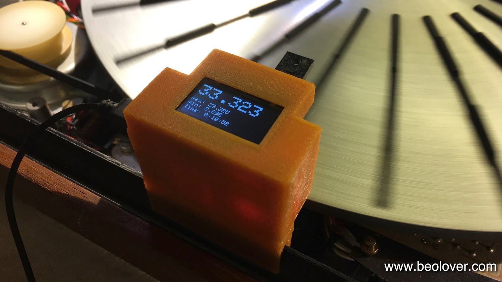
After installing a new gold plated DIN 5 plug, it was time to give this Beogram 4000 a first spin. I adjusted the RPM with my Beolover RPM device:
The precision multi-turn RPM trimmers that I installed recently proved very helpful for this process enabling a very precise adjustment. If you do this at home, let the unit run for 15 min or so before doing it since the RPM changes slightly while the motor and the electronics warm up. The Beolover RPM device is available to other enthusiasts, just send me an email or use the contact form. It comes with a separate base that allows to set it up on the assembled turntable for occasional RPM checking.

The next step was to adjust the chassis and the platter height. A concern with the 400x series is always to get the platter centered. The built in adjustment often does not have enough range for this adjustment. To improve the situation I recently developed a 3D printed part that can be installed on the leaf springs that float the table:
This part pulls the metal string a bit outward, allowing to give the floating sub chassis a tug outward if necessary.
Once the platter is in the right spot, the arm lowering limit can be adjusted:
This is an important adjustment to make sure the needle does not accidentally hit the platter ribs in case of a malfunction of the record detection mechanism (a dead light sensor can for example disable the mechanism, and the arm would lower on the platter even if there is no record).

The next step was to upgrade the counterweight mechanism in the tonearm. The screw that is used to calibrate the weight is held in place with a simple locking clip, which allows it to shift in place a bit:
Considering the necessity to ship the Beogram back to its owner after the restoration this is not acceptable. I usually replace the clip with a M3 nut, which can be tightened down for a more permanent calibration:
After this procedure, I gave the aluminum panels a good cleaning (careful here: do not use any harsh detergents. A mild dishwashing detergent, warm water and a Mr. Magic original eraser pad does the job very well)

The next step was to adjust the tracking weight. I used to do this with a mechanical B&O gauge, but I recently upgraded to a digital scale:
This scale can be obtained from Amazon for less than $15. It has a weight range of 5 g and is pretty accurate. I compared it with the B&O gauge and the reading was quite close. In my opinion there is no reason to spend more money on a tracking weight scale.

And then it was finally time to enjoy this lovely Beogram 4000 for the first time. I selected a recent addition to my fast growing record collection, Freddie Hubbard's CTI issue "Straight Life" (CTI 6007). Of course, I cleaned this record ultrasonically with my CleanerVinyl Pro before listening to it.  Ultrasonic cleaning can make quite a difference when original vintage vinyl is to be enjoyed. This issue is one of the few green label CTI records of the 6000 series and may well be an original pressing. Here is an impression:
I really enjoy the second side of this record, especially the funky "Mr. Clean", but the more calm "Here's That Rainy Day" is also quite lovely. The centerfold has a great picture of Freddie and Herbie on the inside:
I just cannot seem to get enough records of this very creative jazz period. Awesome stuff! 

Sunday, January 29, 2017

Beogram 4000: Replacement of Corroded DIN5 Plug and Installation of a Grounding Switch

After rebuilding the control cluster the next step of my current Beogram 4000 restoration was to replace the original corroded DIN 5 plug with a modern gold plated all-metal plug, and to install a switch that allows connecting system and signal grounds in case there is a ground loop causing a hum in connection with the amplifier. This shows the rusty original plug:
And here the replacement:
Pretty! On to the grounding switch. This shows the terminals where the DIN cable is connected to the internal cartridge wiring:
This is the perfect spot to install the switch:
This switch allows to toggle between the B&O-original setup, where signal and system grounds are kept separate, and a configuration where both grounds are connected. B&O actually adopted this configuration in later 4002 and the 4004 Beograms. My experience is that if there is a hum, this connection in most cases suppresses it.


Friday, January 20, 2017

Beogram 4000: Restoration of the Control Panel - LEDs and Gold Plating of Switch Terminals

After gold plating the carriage position switches, it was time to rebuild the control panel of the Beogram 4000 that I am restoring right now. I usually replace the incandescent light bulbs with LED assemblies, and I gold-plate the switch terminals to ensure trouble-free operation down the road.
This shows the original keypad switch terminals, which were quite oxidized:


I removed the terminals:
And gold coated them after removing the oxidation with a fiber glass pen:
And like with the last Beogram 4000 that I did, I forgot to remove one terminal in my first approach...not funny! Here we go:
and after coating:
Pretty, aren't they?? Then I soldered them back into the PCB:
The next step was to replace the light bulbs with LEDs. This shows them in action:
The position scale illumination bulbs were replaced with my custom designed dual red/green LED assemblies:
These boards are available to other enthusiasts. Just send me an email if you want to upgrade your Beogram 4000!
The bulbs that illuminate the RPM trimmers from the back were replaced with through hole high brightness LEDs that are dimmed with 3.3k resistors:
Using strongly dimmed high brightness LEDs saves more current further reducing the strain on the transformer of the Beogram (which gets pretty warm during play) along with the other LEDs that I implanted.
This is an impression of the LEDs in action:
The red-green LEDs create a very authentic background illumination for the position indicator while the presence of red photons in the LED light ensures that the indicator shows up red like when illuminated with incandescent bulbs.