Beolover provides professional maintenance and restoration services for vintage Bang&Olufsen stereos. We give one year warranty on parts and labor. All parts featured on the blog are available at our Store for DIY. Please, send an email for inquiries. Enjoy the blog!
As usual the original DIN5 plug on the Beogram 4000 that I am currently restoring was badly oxidized. This shows the original plug:
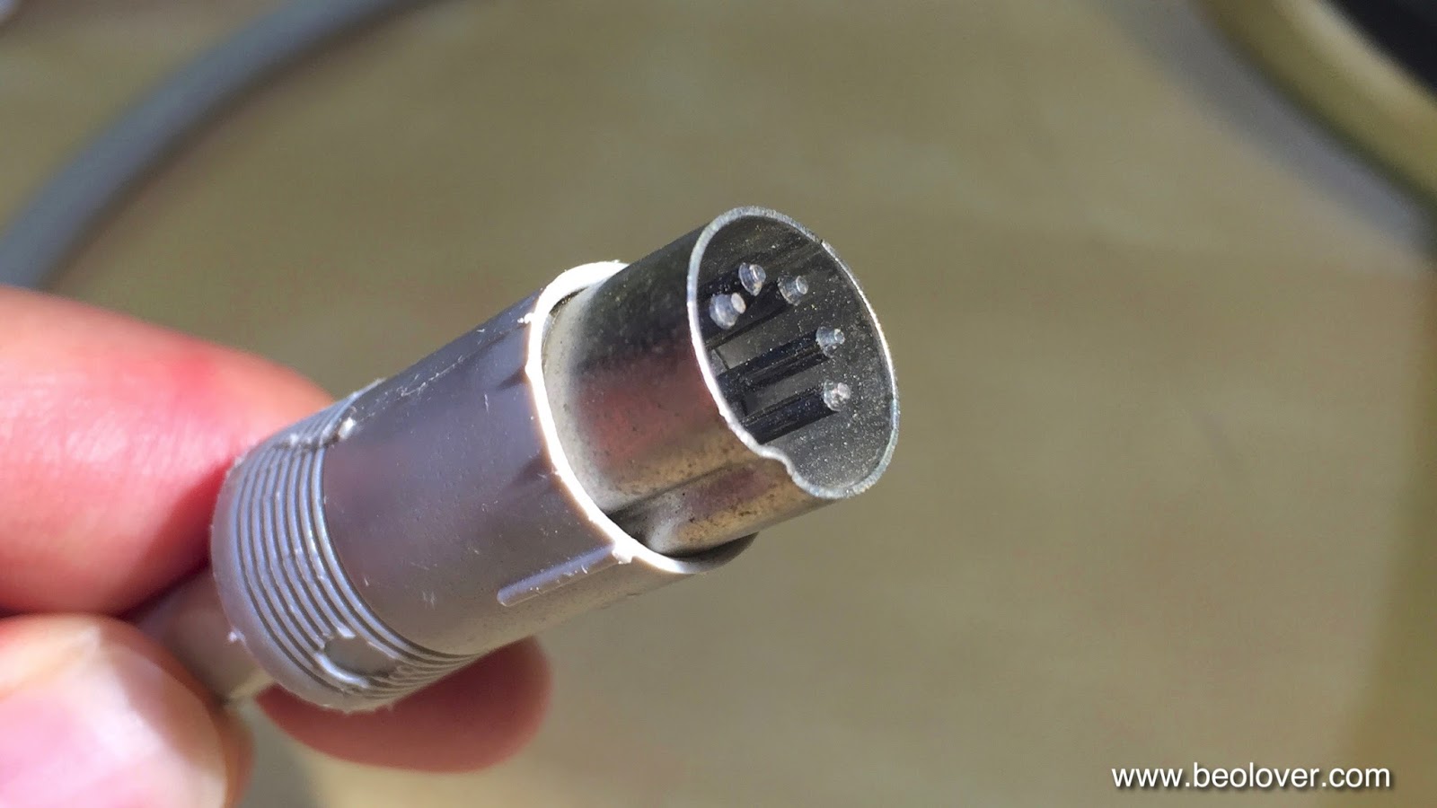
I replaced it with a new all-metal plug that has gold coated terminals:
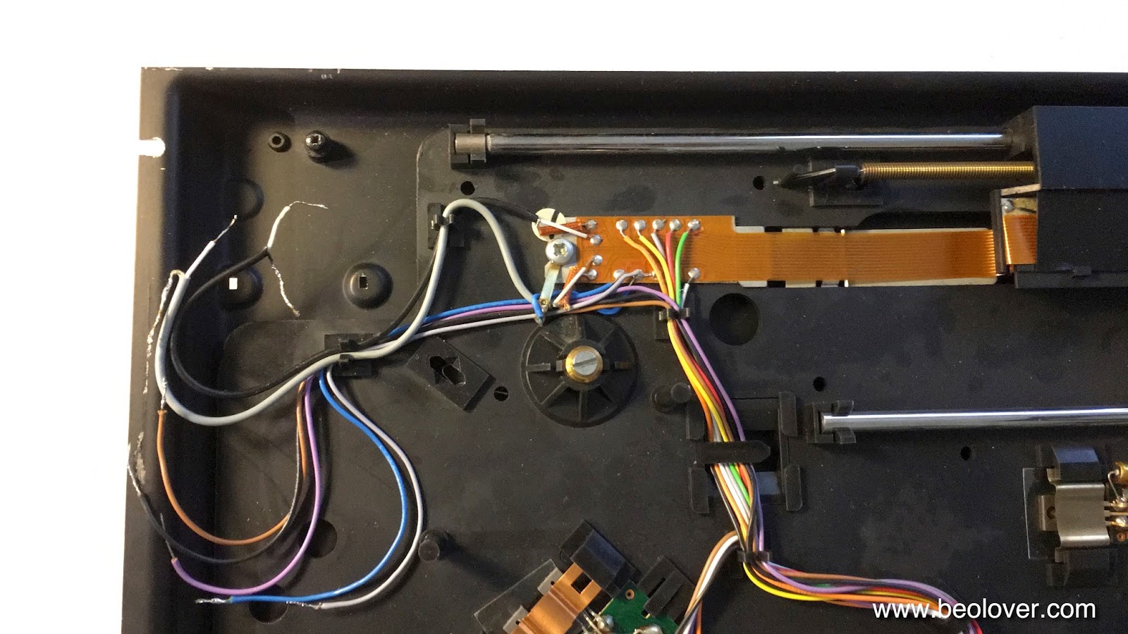
Another useful upgrade of the signal output of any Beogram is the installation of a switch that allows connecting signal and system grounds. This is a useful feature if the Beogram is ever to be used with a DIN5 to RCA adapter. Since RCA cables do not carry the system ground, connecting it to the signal ground on the Beogram often eliminates humming. This shows the output terminal assembly of the Beogram 4000 in its original condition:
This open layout makes it very convenient to add a switch:
The shown switch position connects the two ground. Flipping the switch would open the connection.
The Beogram 4000 that I am restoring right now had a badly corroded and poorly installed DIN 5 plug. Obviously not the original plug. Here are a couple pictures of the sorry state of this plug:
I think the dangling black lead may have been an attempt to reduce some humming issues (no surprise, considering the way this plug was installed...;-). Besides this strange construction, one of the signal leads was also disconnected due to a sad soldering job.
I cut off the plug and prepared the leads for the new plug:
This picture shows the advantage of DIN connections over RCA: The entire cable and connectors are double shielded. Each lead is shielded by the signal ground lead and then there is an outer shield that connects the enclosures of amplifier and turntable. That way the shielding is complete, which gives the best defense against EMI. RCA usually only have a single shield via the signal ground. That is why there is usually a separate wire that connects the amplifier and turntable system/enclosure grounds.
Then I soldered it on:
And this is how it looks with the shield on:
Beogolden I'd say!
The final step of refurbishing the signal path was to install a switch that allows connecting signal and system grounds. This is a convenient features if there is a hum when connecting to RCA inputs via an adapter.
Switch to the left (as shown) and the grounds are connected. Switch to the right and the grounds are disconnected as in the original configuration.
Practically all Beogram 4002/4 and 6000 need their DIN5 plugs replaced due to various levels of corrosion on the contacts, which were not gold plated back in the 1970s. This Beogram 6000 (5512) is a 'beautiful' example:
and with the shield removed:
I cut the rusty plug off and installed a new gold plated all metal plug:
After rebuilding the control cluster the next step of my current Beogram 4000 restoration was to replace the original corroded DIN 5 plug with a modern gold plated all-metal plug, and to install a switch that allows connecting system and signal grounds in case there is a ground loop causing a hum in connection with the amplifier. This shows the rusty original plug:
And here the replacement:
Pretty! On to the grounding switch. This shows the terminals where the DIN cable is connected to the internal cartridge wiring:
This is the perfect spot to install the switch:
This switch allows to toggle between the B&O-original setup, where signal and system grounds are kept separate, and a configuration where both grounds are connected. B&O actually adopted this configuration in later 4002 and the 4004 Beograms. My experience is that if there is a hum, this connection in most cases suppresses it.
The next step in this project was to transplant the DIN7 output assembly from a parts-Beogram 8002 that I acquired from a crooked audio repair shop in Chicago. This unit is now coming in handy here since the 8002 was missing its DIN7 output cluster:
I always wonder what drives people to do such things, but here we are on our interesting little self-absorbed planet...;-).
I extracted the assembly from the parts 8002:
I decided to update the relay with a modern encapsulated unit while I had everything on the bench. The original Omron G2V-2 relay can easily be replaced with its modern G5V-2 cousin, which has the same footprint:
And here is a photo of the installed new relay:
and with its shield clamped on:
This shows the restored wiring:
After verifying that the relay worked properly I installed a grounding switch that allows to connect signal and system grounds if there is a hum problem:
On to the two other issues that I was able to identify: The deck does not detect the absence of records and happily lowers the arm onto the platter. It also has a missing digit in the RPM display. One step at a time.
No restoration of a 4002 is complete without replacing the usually oxidized original DIN5 connector. Those precious low voltage signals deserve the best contacts possible. Gold does not oxidize, and therefore it is able to make low-resistance and long lasting contact. This shows the original plug that was on the Beogram 4002 (5501) that I am currently restoring:
I cut the plug off and prepared the cable for installation of the new gold plated all-metal plug:
Then it was time to solder the plug to the cable:
And this shows the assembled new plug in all its glory:
Beautiful! On to the final touches to get this Beogram ready for primetime!
In my opinion no Beogram 4002 restoration is complete without replacing the usually corroded original output plug(s) with modern all metal units with gold plated terminals. Those precious analog signals deserve only the best! Here are a few impressions of the DIN5 replacement that I just did for the Beogram 4002 (5503) that I am finishing up:
This shows the original DIN5 plug:
This shows the soldering job 'under the hood':
A proper DIN5 installation requires that the shield is separated from the signal ground and that the insulation of the signal leads extends to the solder terminals. All this can be a bit fiddly due to the small space and thin leads one works on.
The Beogram 4002 (5514) that I am currently restoring is making progress. In my opinion a Beogram restoration is only complete with a modern all-metal DIN 5 plug that has gold coated contact terminals. The original plugs are usually corroded and that is not a great thing for transmitting the precious signals from the MMC cartridge. Here is an impression of the original plug with oxidized terminals:
This shows the soldering job inside the new plug:
And here the final result:
Pretty, isn't it?? This is Beolove! On to adjusting the platter and sub-chassis...
The restoration of the signal path is only complete with a gold plated plug, and so I just did it for the Beogram 4002(5513) that I am restoring right now: This shows the sad original oxidized plug:
And here an impression of the internal configuration of the new Rean plug:
Well organized and pretty! And with the all metal enclosure on:
The Beogram 4000 that I am currently restoring had a cutoff output cable:
This is already the third 4000 that I am working on that had a mutilated cable. I really wonder why some people are attracted to cutting off cables...very strange! Anyway this gave me an opportunity to install a modern cable with double braided and foil shielding, which is the best way to keep interference from our precious MMC signals on their way to the amplifier.
I installed a quality Neutrik gold plated all-metal DIN5 plug on the business end of the cable:
I always like the looks of these plugs!
Here is the other end inside the turntable. First I prepared the cable for installation:
and then I soldered it in at the terminal block. This shows the original setup with my standard grounding switch already installed. This switch allows to connect signal and system grounds in case a RCA adapter without grounding breakout is used:
This shows the set-up with the new cable:
All good again in the 'signal path department'! Platter alignment and floating chassis adjustment are next!
After replacing the output relay in the Beogram 4002 (5513) that I am currently finishing up it was time to also get rid of the corroded DIN5 plug. This is how the original plug looked like:
I installed a quality Rean DIN5 with gold plated terminals. Here are a few impressions. This shows the cable prepped for installation:
This shows the installed cable. Space is pretty tight inside these DIN5s. Especially keeping the signal and system grounds separated is challenging:
This shows the plug assembled:
Pretty! Good to know that the precious vinyl signals can now travel to the amplifier unimpeded!
It turned out that fixing the broken out DIN 7 jack of the Beocord 9000 that I just started to work on was easy. The part is exactly the same as they used for the Phono input of the Beomaster 8000. Last year I developed a 3D printed part that can resurrect these sockets when their flimsy tabs break off that normally prevent them from falling into their panel cutout. When the tabs break off due to the force applied while inserting a cable plug the jack gets pushed into the enclosure. Here is a picture of the broken jack:
These are the 3D printed tabs that replace the broken off parts:
I made a short video that shows how to install them and gives a demonstration of the repaired plug:
This shows the end result:
After the DIN jack was fixed and the tape drive was installed back into its spot, I finally gave this Beocord its first spin. I made a recording using the Beomaster 4400 that I restored recently, and I played back a nice mix tape of Donald Byrd tunes from the early 70s that I had recorded a while ago on my own 9000. Lovely!
However: One segment of the display does not work,
and I also found a 'mystery piece' in the Beocord enclosure when I initially took out the drive:
The left part is the one that I found lying at the bottom of the enclosure. The right part is its counter part from the right side of the head carrier assembly. The broken part holds down the left side of the carrier, i.e. it is mandatory that it gets fixed. Otherwise, the heads might be in a non-spec position. I found out about this part in an excellent thread on Beoworld that was started by 'Sonavor' when he rebuilt one of his eight Beocords (kudos to owning that many! It appears, and this should please my wife, I still have a long way to go until my addiction reaches this level!!...;-).
Unfortunately, I was not able to find the 2.5mm bearing ball that goes along with the spring. The ball is needed to let the head carrier slide beneath the spring without generating too much friction. Luckily, I had the second ball for taking measurements and I was able to find small batches of these balls on Amazon Prime, so this may get fixed in a couple of days.