Featured Post

Beolover SyncDrive: DC Platter Motor Replacement for Beogram 4002 and 4004 (Type 551x and 552x)

Late Beogram 4002 and the 4004 (Types 551x and 552x), which have DC platter motors instead of the earlier synchronous AC motors usually suff...

Showing posts with label 151RRBG4002. Show all posts

Wednesday, October 27, 2021

Beogram Commander Remote Control: Successful Test of New 4002 (550x) AC Motor Version

I received a few inquiries about making the Beolover Commander remote module work with AC motor Beogram 4002s. My recent update of the Commander for Beogram 4002 and 4004 only works in DC motor Beograms since AC motor versions have no keypad plug socket on the main PCB. Their keypads are hard wired to the PCB. So I thought it would be nice to offer an AC version. But this made a redesign of the Commander module necessary.

This shows the redesigned version:


The main difference between DC and the presented AC version is an additional small breakout PCB (the long and narrow item on the picture) that can be soldered to the keypad wire-to-board solder pads. It feeds the keypad signals into a small connector that then connects to a matching connector on the Commander board. That is what the green jumper is for. The final version will come with a custom made jumper that has an appropriate length.

I thought it would be perfect to celebrate the arrival of the AC Motor Commander by implementing it for the first time in a rare early 5501 version (the first 4002 series they ever made after discontinuing the original 4000). This 5501 Beogram recently revisited my work bench from Australia due to the malfunction of the solenoid transistor and a non-working carriage motor. My customer agreed to let me delay return shipment to try out the AC Commander on his precious deck! Thank you very much!

The first step of the installation was to solder the breakout to the keypad PCB. This shows the original PCB after extracting it from the keypad assembly:


The wire harness from the main PCB connects to the pads up front from below. The two resistors on top are 22k pull-ups for the 33 and 45 RPM transistors, which seem to have been added after the fact due to operability issues in this early version. In later AC motor versions the PCB was changed and the resistors are placed on dedicated solder pads on the central part of the PCB. 
Unfortunately, on the 5501 they are a bit in the way of installing the Commander breakout board. When I tried to push them slightly out of the way for removing some of the solder on the pads, one broke apart:

I replaced them both with 20k resistors that I had in my stash. The 10% different value is not important, they only pull up the RPM switch transistors to make their ON/OFF states more reliable.
This shows the two resistors in place. They now allow some room for Commander breakout PCB:

The next step was to solder the breakout across the pads, which was easily done by putting some flux on the pads and then touching their orthogonal contact area with the soldering tip carrying a bunch of solder:

This is how it looks when the PCB is inserted back into the keypad:


The next step was bolting the Commander onto the main PCB and connecting the two connectors with the green jumper:

Then came the moment of truth, when I powered the deck up. And hurray, no magic smoke arose!

So I flashed the chip. The next step was pairing the Apple remote to the Commander board.

On the DC version Commander this involves pressing two buttons for ~6 min until the 33 RPM light comes on and the platter moves very briefly, indicating the completion of the pairing process.

I did the same here: And nothing happened! Panic arose, but pressing the Start button on the remote set the carriage in motion! So it seemed to have paired properly! 

And then it dawned on me: The AC versions does not have the 'record cleaning function', which is activated by pressing the 33 RPM key with the carriage in its home position. On the DC versions, pressing 33 RPM simply sets the platter in motion until the key is let go again. This is very convenient for wiping the platter before playing the record.
B&O probably introduced this function with the DC motor since the DC motor has a much lower torque than the AC motors, causing strong RPM fluctuations during swiping the platter. On AC motor units one can wipe the platter while the music plays, and there is almost no RPM slowdown. But with the DC motor one has to do it before actually pressing START for listening.

Anyway, so far so good! V1.0 seemed to work!

But the above made me think: It would be nice to have a record swipe functionality like on the DC models! And of course the pairing process feedback needed to be changed.

So I changed the code:
  • Instead of the 33RPM/platter twitch response to a completed pairing process, now the auto-repeat LED briefly lights up.
  • Now one can press the 'select' button on the remote for platter swiping like on a DC Beogram. This was done by replacing the absent swipe circuitry by a combination of activating START and then immediately "<" to stop the motion of the carriage. So it only moves a few mm until the 'shut off (SO)' switch is cleared that the deck can run the motor. Subsequent release of the select button activates the STOP function and the carriage goes back home and the platter motor goes off. What would we do without microcontrollers these days!!...;-)
Beolovely!! I estimate the AC Motor Commander should become available in 2-3 weeks when I will hopefully have received the proper jumpers for connecting keypad breakout and Commander board. Stay tuned!


Saturday, June 9, 2018

Beogram 4002 (5501): Random Stop Issue Fixed - Defective Photo Resistor in the Spindle RPM Sensor

A Beogram 4002 (5501) that I restored last year developed a strange new problem: When playing a record the OFF (>>) function  would be triggered randomly during play as if someone pressed the >> key on the keypad.
Before I will discuss the fix, let's have a look at the circuit diagram (click on the diagram to get it in full resolution):
TR17 in the 'Electronic Switch' is responsible for triggering the >> function of the turntable. Whenever its base is pulled to GND its collector goes high to ~18V and then the arm is lifted and the carriage is driven home. There are three ways this can occur: Via two mechanical switches, one being the "End Switch" (ES) under the carriage and the other the ">>" key on the keypad. The End Switch is the one that sends the carriage back whenever it is driven all the way to the left (i.e. manually via the << key or automatically if there is no record on the platter and the arms go all the way searching for one).
The third way to trigger >> is via the end groove detection mechanism ("RUN-OFF STOP" on the diagram). This works via TR20 whose base is pulled up when the end groove is detected. That connects its collector to ground, and with that the >> function is activated.
The end groove detection mechanism works via an 'analog rotary encoder' that detects light flashes impinging on a photo resistor (OR2) from a bulb (OIL1) that shines its light though four holes in the carriage pulley as they pass by (creating light fluctuations on OR2). 
These light pulses short OR2 to GND causing TR21 to shut down, which increases the voltage at the collector of TR21 to about 19V. These voltage pulses (see oscilloscope trace schematic on the circuit diagram) charge C33, which, via the voltage divider formed by R88/89, pulls up the base of TR20, triggering the >> function.
It is interesting to to note that the bulb OIL0 only comes on when its switch to GND is closed. This switch is activated by the carriage when the tone arm gets close to the record label. This switch is activated by the same tab on the carriage assembly that activates the 17 cm (singles) set-down point switch ("B" in the service manual). This is the reason that the tab that activates B has a long flat shape. Anyway, this switch aims to prevent triggering the the RUN-OFF STOP mechanism when the carriage briefly moves faster between two tracks of a record when the carriage is still far away from the label.
Why does the mechanism not trigger RUN-OFF STOP when the carriage advances normally while playing the last track when OIL1 is already on? C34, R91 and D30 form a network that discharges C33 when there is no light on the sensor. This means there is a competition between charging during illumination episodes, and discharging when there is no light on the sensor. So if the pulley rotates only slowly and occasionally during playback of a track, discharging 'wins' and the base of TR20 is not pulled up high enough. But when the light flashes happen quickly like when the carriage moves fast pulled along by the end groove, then the charging mechanism wins and TR20 is turned on. The beauty of analog control systems!!

Ok, back to the 'Random Stop Issue': After verifying that the ES and OFF switches were working properly, I traced the signals from the base of TR17 into the RUN-OFF STOP circuit. This shows the oscilloscope traces that I measured:

The traces are assigned as follows:

  • Yellow: TR17 collector (when this signal goes high the measurement was triggered - the graph shows ±5 sec around the >> event)
  • Blue: TR20 base
  • Green: TR21 collector
  • Red: TR21 base
These traces show that before the >> event happens there is a random statistical fluctuation of the voltage at the collector of TR21 (instead of being close to GND if there is no end groove event). These voltage flashes obviously correlate with the signal at the base of TR21 (suggesting that TR21 is working properly). This leaves only one conclusion: The sensor OR2 randomly short circuits to GND causing these voltage spikes. These spikes can be enough to charge C33 and when the voltage one C33 gets high enough due to these random events, the >> function is triggered. This is seen in the blue trace, which shows that the voltage exceeds the ~0.6-7V threshold needed to turn on a standard silicon based transistor when TR17 is activated.

All this told me that OR2 was faulty. This meant it needed to be replaced. Since this is a special B&O part, which is not available anymore, I decided to design a 3D printed assembly to replace the entire bulb/sensor assembly on the pulley. This shows the setup after I implanted an LED to replace the light bulb last year:
The orange part contains the LED (Newark 78R6602) and its 2k current limiting resistor (Newark 26R3983). It was designed to stick onto the OR2 sensor housing. The current design replaces the entire encoder setup. These are the structural parts of the assembly:
Assembled they look like this:
And with LED, resistor and photo resistor (type "5516", ~10k resistance when dark, ~500 Ohm when illuminated) installed:
And after installation and in action:
Once the set-up was installed I measured the signal at the collector of TR21 when the LED came on:
This signal looks pretty much like what the manual demands. I tested the Beogram by playing some records, and it seems everything is working again! So I am hopeful that this fix took care of the issue.


Wednesday, March 8, 2017

Beogram 4002 (5501): Repair of 'Knocking' AC Motor

I usually like to take my time for testing Beograms that I restored to make sure there are no intermittent issues. Sometimes also additional problems arise when one starts using them again on a routine day-to-day schedule. And so it happened with the AC motor Beogram 4002 (5501) that I completed recently. After playing a number of records I noticed a faint 'knocking' coming from under the hood. After removal of the aluminum plates I realized that the knocking was in sync with the rotation of the AC motor. First I tried to adjust the motor tilt, which brought some reduction of the noise, but after a while it always came back, and it also grew in intensity the more records I played until it was clearly audible whenever a quieter track was playing. Absolutely unacceptable for a turntable!

There was only one option: Take the motor apart and have a look! This shows the motor installed (with my 3D printed capacitor adapter in the background):
I removed it from the enclosure. Unfortunately, the AC motor is soldered in, i.e. one has to unsolder the leads to take it out:
This motor is held together by two rivets with M3 threads that also serve to hold the leveling screws. Sometimes these rivets have already failed at this age of the Beogram and it is easy to extract them, but not in this case. I had to remove them with force. One of the came out by applying a bit of pressure with adjustable pliers:
With the other one I was not that lucky and I had to drill it out on my work bench. After that was accomplished the motor opened up:
This shows the rotor and the parts that are on the shaft:
this shows one of the Oilite brass bearings:
They look very similar to the bearings that are in the later DC motors.
Unfortunately, one cannot easily extract them. Or at least I did not see an obvious way, and in the absence of a spare motor to replace this one, I elected to leave them in place of the oil infusion process. This meant I had to put in the entire motor housing into my mason jar and put it under vacuum:
The usual bubbles formed after the vacuum was pulled. After 24 hours I took the parts out and drained the oil onto an absorbent paper towel for another 8 hours. then I wiped everything dry of oil. This process worked fairly well. I put the motor back together. In absence of replacement rivets I designed 3D printed parts outfitted with M3 nuts to hold the adjustment screws. This shows the part on the side facing away fro the enclosure:
and on the enclosure side (there is less space, i.e. it had to be a bit more spartan):
This shows the motor installed with these parts:
When the motor is bolted in like this it is held together securely by the two mounting screws that are in the two other orifices in the motor housing.

Testing of the motor after this procedure demonstrated that the knocking was gone and that the RPM was stable. I guess the lesson learned here is that the 4002/4000 AC motors also needs restoration at this point in time to re-infuse the dried out bearings with oil. But it seems the issue may be a bit rarer than in the DC motors, where almost all of them seem to be afflicted by dry bearings. I am hypothesizing that this difference may be related to the lower RPM of AC motors, which should consequently result in less oil being removed from the bearings per number of played records. 


Saturday, November 19, 2016

Beogram 4002 (5501): Installation of New Aluminum Pulley for the Carriage Servo

A few weeks ago I finished up the restoration of a Beogram 4002 (5501). The only item missing was a new aluminum pulley for the carriage servo. As usual this unit had a cracked pulley that was wobbling quite a bit, and that caused some noise and vibration when the carriage was driven fast like during start or stop. Absolutely not beolovely!

Unfortunately, the normal pulley design that Nick provides for my restorations of these Beograms does not work in the early 5501 types since they have a unique end groove detection mechanism requiring a pulley with four holes that act as optical chopper to detect the speed of the carriage. If it gets fast, and the end groove switch is activated the STOP sequence is activated and the arms travel to the home position. 

I already replaced the light bulb of this mechanism with a LED based fixture, and now I was finally able to add the proper pulley. Nick just sent me a few redesigned pulleys for the 5501 type. Here is an impression of the new pulley together with the original cracked one:
This shows it installed together with my LED based illumination setup:
And since it looks so beautiful (at least in the eyes of the Beolover...;-), here is a photo of the setup in action:
And after playing a few records with the new pulley, I am happy to report that it works very well. The holes are in the right position and they have the proper diameter to be able to trigger the end groove detection mechanism. So this baby may be close to go on its trip home back to the UK! But I will still play it a bit more to make sure that there are no intermittent issues left before it goes on its long trip.

This is what is playing right now:
And an impression from the inside of this lovely gatefold cover:
My Gabor Szabo and Chico Hamilton collection is growing rapidly. This is just amazing stuff. Cannot get enough! Must go buy more shelves for more records!...;-)


Thursday, October 20, 2016

Beogram 4002 (5501): Final Touches - AC Motor Calibration, Adjusting Platter and Sub-Chassis and Tracking Force

The restoration of the Beogram 4002 (5501) that I am currently working on is coming to an end. I gave the aluminum panels and the platter a deep clean, and then did the sub-chassis and platter height adjustments followed by an adjustment of the tonearm lowering limit and the tracking weight.


There are two videos on my YouTube channel that show how to adjust the platter bearing and the subchassis (in a Beogram 4000, but the process is very similar in the 4002). There is also a video on my youTube channel that shows how to adjust the lowering limits. This is a very important procedure since the control system of the 4002 cannot guard against photosensor failure in the sensor arm. If the sensor fails the arm will be lowered whether there is a record or not, possibly endangering a very expensive cartridge. The correct adjustment of the arm lowering limit can prevent stylus failure if that happens. And finally, there is also a video about the tracking force calibration process.

After all that was done, I adjusted the AC motor waveforms. This is done by connecting an oscilloscope to the connection point between the motor capacitors and ground:
Then the oscillator trimmer is adjusted until clean waveforms of maximum amplitude are achieved. The end result looked like this for 33 RPM:
and for 45 RPM:
Then I adjusted the RPM precisely with my BeoloverRPM device. Personally, I still use the original design. The updated design is available to other enthusiasts. The BeoloverRPM is very convenient for the occasional RPM adjustment (yes, the belts do become elongated over time causing the RPM to slowly drop). Here are two pictures showing my adjustments for this Beogram with its new belt:
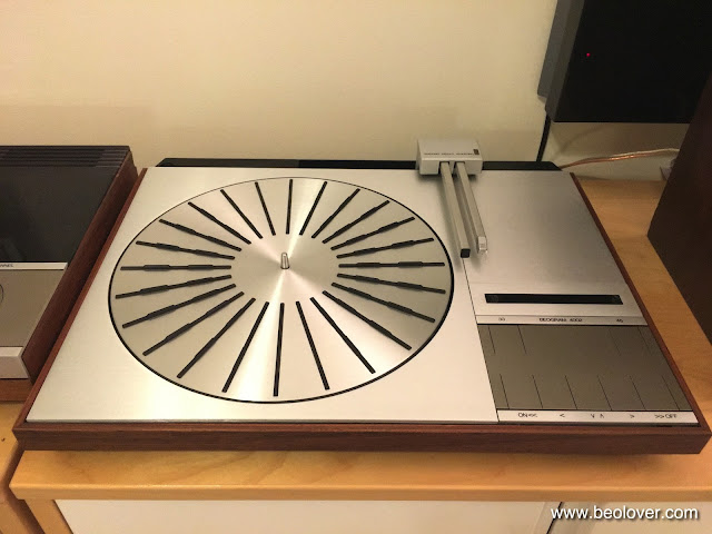
Very nice! And then it was time to set the unit up next to my Beogram 6000 4-Channel:
I celebrated this restoration with a record that I just bought: Gabor Szabo's "The Sorcerer":
This record is rapidly becoming one of my all time favorites. An amazing live concert recording that has a remarkably raw power that sucks you into Szabo's rhythm. 


Wednesday, October 19, 2016

Beogram 4002 (5501): Replacing the Original DIN5 Plug with a Modern All-Metal Gold Plated Unit

No restoration of a 4002 is complete without replacing the usually oxidized original DIN5 connector. Those precious low voltage signals deserve the best contacts possible. Gold does not oxidize, and therefore it is able to make low-resistance and long lasting contact. This shows the original plug that was on the Beogram 4002 (5501) that I am currently restoring:

I cut the plug off and prepared the cable for installation of the new gold plated all-metal plug:
Then it was time to solder the plug to the cable:
And this shows the assembled new plug in all its glory:
Beautiful! On to the final touches to get this Beogram ready for primetime!


Monday, October 10, 2016

Beogram 4002 (5501): Sensor Arm Light Bulb Replacement - Final Version

This is a follow up to my recent post about the replacement of incandescent sensor arm bulbs in Beogram 4002 turntables with a LED setup. Subsequent experiments revealed that the best position for the LED PCB is when it is pushed down by about 2.5 mm into the bulb cavity of the sensor compartment. This position yields the highest sensor response as measured at the collector of 1TR8 (5501; pre SSN 257556 notation), and I think this makes sense since the light bulbs have the filament always a bit lower than the upper rim due to the glass bulb.
I like reproducible solutions, and so I designed a small 3D printed wedge that can be epoxied on the outside of the flexPCB and that presses the LED down by the correct amount when the bulb compartment is closed:
This shows the LED powered up at 5.5V:
The board has a ballast resistor that adjusts the current draw to the prescribed ~60mA. This is necessary that the 'bulb malfunction detection circuit' is not triggered on the main PCB of the Beogram.

This shows the board installed and lit up:
This shows the TR8 signal:
Note how nicely the curves bottom out at 0V.

This shows the setup 'in action':
Note the nice red-orange glow of the B&O logo. This is a result of using a 2600K color temperature high intensity white light LED that has a considerable amount of red light in its emission spectrum which enables a 95% color rendering index (CRI). Also the light spot is nice and tight indicating that the light source is in the focal point of the exit collimator.
This pretty much concludes the development of the LED implant for the Beogram 400x sensor arm. Henceforth Beolover restorations can (if so desired by my customers) yield Beograms devoid of incandescent bulbs.


Thursday, October 6, 2016

Beogram 4002 (5501): Replacing the Sensor Arm Bulb with a SMD LED on a FlexPCB

***************************Sequel to this post see here******************************

I finally was able to design a LED based upgrade to replace the sensor arm incandescent light bulb in Beogram 4002 units. This was the most difficult bulb to replace due to the tight space available in the sensor arm and the requirement to put out an incandescent looking light spot, while being able to properly back-illuminate the lovely orange-red B&O logo at the end of the arm. 
I quickly realized that only a flexPCB would be able to do the trick. My first experiments involved high brightness amber LEDs combined with a red LED to provide some longer wavelength photons to give the B&O logo a more red appearance. Here is an impression of the design:
While this worked technically, the light spot on the record was way too orange, while the red LED could not compete with the amber unit:
Worse, the red LED could be seen reflected in the record surface separated from the amber spot due to the different projection of the red LED through the lens that focuses the light on the record surface. Anyway, this was not Beolovely, and so I did some research and finally found a latest-development warm white LED with a 95% color rendering index (CRI) value, which promised that this LED would be able to correctly illuminate the B&O logo while looking fairly natural when reflected from the record. This is how my board looked like with it on there:
And fired up:
It is a pretty warm white (2600K temperature equivalent). And this shows the board folded into the sensor arm cavity:
And in action:
Pretty authentic look, even though of course the light spot is not a projection of a bulb filament, i.e. it is a bit more homogeneous than the original bulb pattern. But I think without pointing this out to someone, it would be hard to tell that a white LED is at work here. So far so good...but the real test is of course whether this setup can make enough signal at the sensor output for a reliable detection of the absence of a record. For this I measured the sensor signal on the platter without a record present. This is the signal after being amplified by TR8:
Note that the dips go all the way to zero, which is what is required to properly disable arm lowering when there is no record. Bulbs rarely deliver a stronger signal, so this seems adequate!
Another critical factor is the current draw of the LED board. The Beogram 4002 is equipped with a detection circuit that disables arm lowering if the bulb filament breaks. This circuit requires about 50-60mA in the bulb circuit to enable arm lowering. So I added a resistor to the LED board to match 60mA (the LED on its own only draws about 40 mA...). This shows my bench power supply driving the board with 5.5V (same voltage as is applied to the bulb in the sensor arm):
It appears we have a functioning prototype in play! All that needs to be done now is to clean the board design up a bit to arrive at a final version. This is Beolove!