Featured Post

Beolover SyncDrive: DC Platter Motor Replacement for Beogram 4002 and 4004 (Type 551x and 552x)

Late Beogram 4002 and the 4004 (Types 551x and 552x), which have DC platter motors instead of the earlier synchronous AC motors usually suff...

Showing posts with label stop. Show all posts

Thursday, November 28, 2024

Beogram 4002 (5524): A Fun Afternoon with the Electronic Switch

I am making good progress with the restoration of a Beogram 4002 (Type 5524) that I recently received from Singapore.

Excitingly this unit exhibited an hitherto unexperienced issue:

After rebuilding the PCBs I tested the unit. After pressing START (<<) the following happened:

The carriage started moving and the solenoid immediately engaged lowering the arm. When I let the START key go, the carriage immediately stopped with the arm down. Only continuously pressing the START key kept the carriage moving. The arm would always go down as soon as I let the key go.

The STOP (>>) key behaved similarly: The arm lifted and the carriage started moving back home, but as soon as I let the key go, the carriage stopped.

Normal behavior would be that the carriage keeps going after pressing the START or STOP keys, and only <, >, and up/down would stop it.

After a bit of head scratching I thought that most likely one of the two transistors in the Electronic Switch responsible for arm lowering/lifting (TR14/15) might be malfunctioning. I replaced them on this hunch and tried again. But no cigar, this did not fix it!

Very strange, I thought! So I implanted the main PCB of this Beogram into my own 4002 and pressed START. Everything worked perfectly: The carriage kept moving after I let the START key go, and it stopped at the LP setdown point and the solenoid engaged to lower the arm.

This immediately suggested that the board was o.k., and that the problem originated from a component not on the board! But what could influence the Electronic Switch and solenoid in this way? There is really nothing off the main board that participates in the active control of the Beogram except the keypad and the board underneath the carriage that contains the carriage position sensor. 

I put the board back into the unit from Singapore and exchanged the keypad with one of my own. Nothing changed. Then I replaced the carriage PCB with the position sensor. Also no effect. Same behavior.

The only connector on the main board untried at this point (except the RPM panel, which I ruled out based on its purpose in this design) was P4. So I pulled the header out and tried again. This restored the normal << and >> behaviors, i.e. the carriage kept moving until I pressed another button. Of course the arm would not lower with P4 unplugged since the solenoid gets powered via this connector. But this told me that something connecting via P4 was most likely the culprit! Promising!

So I broke out the P4 connections with some jumper wires:

This allowed me to disconnect each of the 10 signals individually and see if this would change the behavior.
And lo and behold, when I got to pin 6 and tried again after disconnecting it, everything worked normally!
This was a bit of a surprise since P4-6 carries the signal for the output relay on the output board, i.e. it is not an input to the main board circuit, but an output from it for controlling the output board!

I looked at the circuit and it occurred to me that this pin has access to the base of the solenoid activating transistor TR9 as well as to the bases of the Electronic Switch transistors TR12 (<<) and TR13 (>>) via R69 and R73. The plot thickened!
This shows the relevant section of the main PCB circuit diagram (click on the diagram to see it in full resolution):
Pin 6 of P4 connects to the base of TR9, which needs to be pulled up to activate the solenoid. This connection basically causes the output relay on the output board to activate as soon as the solenoid gets activated. The base of TR9 also connects to the electronic switch since it gets activated from there (dashed red line). If we turn this around, of course P4-6 could be used to control the solenoid and influence the electronic switch!
This diagram shows the circuit on the output board:
Normally the signal for the relay activation comes in on pin 1 of P8 on this board. It basically turns on 8IC1 once 8C1 is charged up sufficiently (this results in a delay until after the needle pops into the groove). Once 8IC1 is conductive, the relay engages and the outputs are opened up.
After I understood this connection it occurred to me that most likely 8IC1 was the root cause of the observed malfunction! I measured the voltage at P4-6 after pressing << and got 13.5V, which is plenty for activating TR9, TR12 and TR13. 
I replaced 8IC1 with a MPSA13 Darlington and tried again. Everything was working again properly! The carriage found the LP setdown point and the solenoid activated. Beolovely!
On to completing the restoration after an afternoon of fun exploration of the Beogram 4002 circuit!..;-).

Addendum in Proof:

I guess I was not done yet. After a few more tests the newly implanted MPSA13 Darlington died again and the immediate solenoid activation returned.  I should have asked myself yesterday why 8IC1 had died in the first place!...;-). I immediately knew where to look: The spark snubber diode 8D2 that short circuits the inductive voltage peak when the relay turns off when the arm is up. I extracted it and tested it with my transistor tester:

It had become a 6.6 Ohm resistor! I replaced it with a beefier 1N4004 and put in another MPSA13 (a great idea to buy such components by the bag...;-):

And everything was ok again! Let's see how long this will last! The joys of beoloving!...;-)

Saturday, June 9, 2018

Beogram 4002 (5501): Random Stop Issue Fixed - Defective Photo Resistor in the Spindle RPM Sensor

A Beogram 4002 (5501) that I restored last year developed a strange new problem: When playing a record the OFF (>>) function  would be triggered randomly during play as if someone pressed the >> key on the keypad.
Before I will discuss the fix, let's have a look at the circuit diagram (click on the diagram to get it in full resolution):
TR17 in the 'Electronic Switch' is responsible for triggering the >> function of the turntable. Whenever its base is pulled to GND its collector goes high to ~18V and then the arm is lifted and the carriage is driven home. There are three ways this can occur: Via two mechanical switches, one being the "End Switch" (ES) under the carriage and the other the ">>" key on the keypad. The End Switch is the one that sends the carriage back whenever it is driven all the way to the left (i.e. manually via the << key or automatically if there is no record on the platter and the arms go all the way searching for one).
The third way to trigger >> is via the end groove detection mechanism ("RUN-OFF STOP" on the diagram). This works via TR20 whose base is pulled up when the end groove is detected. That connects its collector to ground, and with that the >> function is activated.
The end groove detection mechanism works via an 'analog rotary encoder' that detects light flashes impinging on a photo resistor (OR2) from a bulb (OIL1) that shines its light though four holes in the carriage pulley as they pass by (creating light fluctuations on OR2). 
These light pulses short OR2 to GND causing TR21 to shut down, which increases the voltage at the collector of TR21 to about 19V. These voltage pulses (see oscilloscope trace schematic on the circuit diagram) charge C33, which, via the voltage divider formed by R88/89, pulls up the base of TR20, triggering the >> function.
It is interesting to to note that the bulb OIL0 only comes on when its switch to GND is closed. This switch is activated by the carriage when the tone arm gets close to the record label. This switch is activated by the same tab on the carriage assembly that activates the 17 cm (singles) set-down point switch ("B" in the service manual). This is the reason that the tab that activates B has a long flat shape. Anyway, this switch aims to prevent triggering the the RUN-OFF STOP mechanism when the carriage briefly moves faster between two tracks of a record when the carriage is still far away from the label.
Why does the mechanism not trigger RUN-OFF STOP when the carriage advances normally while playing the last track when OIL1 is already on? C34, R91 and D30 form a network that discharges C33 when there is no light on the sensor. This means there is a competition between charging during illumination episodes, and discharging when there is no light on the sensor. So if the pulley rotates only slowly and occasionally during playback of a track, discharging 'wins' and the base of TR20 is not pulled up high enough. But when the light flashes happen quickly like when the carriage moves fast pulled along by the end groove, then the charging mechanism wins and TR20 is turned on. The beauty of analog control systems!!

Ok, back to the 'Random Stop Issue': After verifying that the ES and OFF switches were working properly, I traced the signals from the base of TR17 into the RUN-OFF STOP circuit. This shows the oscilloscope traces that I measured:

The traces are assigned as follows:

  • Yellow: TR17 collector (when this signal goes high the measurement was triggered - the graph shows ±5 sec around the >> event)
  • Blue: TR20 base
  • Green: TR21 collector
  • Red: TR21 base
These traces show that before the >> event happens there is a random statistical fluctuation of the voltage at the collector of TR21 (instead of being close to GND if there is no end groove event). These voltage flashes obviously correlate with the signal at the base of TR21 (suggesting that TR21 is working properly). This leaves only one conclusion: The sensor OR2 randomly short circuits to GND causing these voltage spikes. These spikes can be enough to charge C33 and when the voltage one C33 gets high enough due to these random events, the >> function is triggered. This is seen in the blue trace, which shows that the voltage exceeds the ~0.6-7V threshold needed to turn on a standard silicon based transistor when TR17 is activated.

All this told me that OR2 was faulty. This meant it needed to be replaced. Since this is a special B&O part, which is not available anymore, I decided to design a 3D printed assembly to replace the entire bulb/sensor assembly on the pulley. This shows the setup after I implanted an LED to replace the light bulb last year:
The orange part contains the LED (Newark 78R6602) and its 2k current limiting resistor (Newark 26R3983). It was designed to stick onto the OR2 sensor housing. The current design replaces the entire encoder setup. These are the structural parts of the assembly:
Assembled they look like this:
And with LED, resistor and photo resistor (type "5516", ~10k resistance when dark, ~500 Ohm when illuminated) installed:
And after installation and in action:
Once the set-up was installed I measured the signal at the collector of TR21 when the LED came on:
This signal looks pretty much like what the manual demands. I tested the Beogram by playing some records, and it seems everything is working again! So I am hopeful that this fix took care of the issue.


Friday, April 20, 2018

Beogram 4002 (5513): First Contact and Two Dead Transistors

I recently received a Beogram 4002. The owner already had started working on it, but then decided to send it over for some trouble shooting. This shows the unit:
It is in pretty good condition. The aluminum parts are almost pristine except a few small scratches in the platter. The keypad has the usual wear pattern and some blank spots on the START button. I took out the aluminum panels and had a look:
When I plugged it in and pressed start, the platter motor started running but the carriage would not move at all. Pressing start results in turning on of TR12 whose collector then goes to about 17V. This voltage turns on TR19 in the H-bridge that controls the carriage motor. I checked the presence of the 17V at TR19 when pressing start. The voltage made it there indicating that TR12 was o.k. Then I checked the voltages at TR20 when TR19 was activated. This test showed that TR20 would not turn on. I extracted it from the board and indeed a transistor tester revealed that it was burned out. I replaced the transistor with a new one, put the board back in place and voila, pressing start activated the carriage.

However, after moving about 2-3mm out, it immediately returned to the home position as if STOP was pressed immediately after start. I checked the voltage at the base of TR13, which controls the stop function. The voltage there was consistently 0V, indicating that either something pulled the base down to 0V or that TR13 itself had a problem. First I checked the start and end switchers, which can pull the base down, but both switches worked properly. Then I extracted TR13 and the transistor tester showed it to be damaged. I replaced it with a new transistor and then everything worked. Pressing start launched the carriage and it found the set down point for LPs and the arm lowered. Then it started racing towards the center of the platter, indicating that the tracking feedback needed some adjusting. Here is a picture of the two extracted transistors:
This Beogram is on the way to recovery!


Thursday, April 5, 2018

Beogram 4000: An Entertaining Evening Exploring the Differential Stop Circuit

Before we send a restored unit back to a customer, we always give them a good 'real world' test, where we simply play a bunch of lovely music over a couple weeks and observe if everything works consistently. The listening part is of course part of the fun of Beoloving! There is always music in the work shop! The case of a recently restored Beogram 4000 is a proof in point of the usefulness of such testing phases: While playing a number of records, I noticed that occasionally the arm would not return to the home position once the end groove had been reached. Normally, the Beogram 4000 detects the end groove spiral due to the higher speed of the carriage and then lifts the arm and returns the carriage. Not in this case, though, where the needle simply went all the way in and then kept playing the final turn over and over again...tock...tock...tock...not very Beolovely!

The problem was that this would only happen occasionally, but most times everything would be fine. Such problems are hard to troubleshoot. In the beginning I thought it was simply a MV switch issue (most 4000 issues come from not working switches), but since I had coated the switch terminals with gold, tests demonstrated that the switch was working very reliably. So I concluded the problem must be in the differential stop circuit, which produces the logic DS level that tells the control system that it is time to lift the arm and return the carriage home. This shows the relevant part of the Beogram 4000 circuit:


This is how it works: The detection of the end groove is done via the carriage motor voltage. Since the end groove typically makes the carriage move faster, the motor voltage is larger than during normal play back of a track. That is why the circuit is called Differential Stop (DS), the end groove is not determined by the position of the arm, but by its velocity towards the center of the record. One of the issues is that the arms do not only move faster in the end groove, but also between tracks and in the run in groove at the outer rim of the record. This problem is solved by introducing a carriage activated switch ("MV") that enables the DS circuit only close to the end groove region of the record. This switch is on the second circuit diagram of the 4000 and it connects MV and MV' in the above circuit snippet.
So when the carriage reaches a point about 65mm away from the center of the record MV and MV' are connected. This causes the voltage that is applied across the motor to be applied across base and emitter of TR24 via 1R54 and trimmer 1VR4. The trimmer is used to adjust the carriage speed threshold at which TR24 turns on (this adjustment turned out to be the critical item during this exploration...read on...;-). When TR24 turns on due to high carriage speed, it then turns on TR23 which serves as an additional input that allows other functions of the turntable to disable the DS circuit (mainly system requested and manual FF function via TR25). When TR23 turns on TR22 becomes conductive and grounds its collector. This causes the logic signal DS to go to 0V. DS then activates carriage return via the logic ICs in the control panel. This immediately turns off the DS circuit since the motor voltage reverses (the MV switch remains closed until the carriage clears the switch on the way back to home position). The result is an about 5-10ms pulse at DS as is shown in this oscilloscope snap shot:
The blue trace is the DS signal. Green and yellow are the (motor) voltage measured on both ends of the MV switch against GND (since it is closed at this moment both traces are the same).
We see that when the motor voltage changes due to the reversal of the carriage direction the pulse terminates.

Ok after this circuit discussion...back to the 'issue' that I was trying to solve, the occasional not working of the DS mechanism:
After I verified that the MV switch worked reliably, I thought the issue must be an intermittent problem with the DS circuit. Since the issue was very intermittent, I used an Arduino as event recorder:
I used one of the pin change interrupts to detect the state of DS and print it out on the serial port whenever it would change from 6V to 0V, i.e. when the circuit activated DS. Then I played some records and waited for the issue to happen. Luckily the second record I played triggered the issue. And, guess what, DS indeed did not change. This told me that the issue is in the circuit. I played another record, and it worked again. Then I put on the previous record and it happened again! This finally turned on some light bulbs in my head. I put the other record on and it worked again! The light became very bright in my head and I concluded: It is the record, dummy! The circuit was basically working, but the records are different! This shows the end grooves of the two records in comparison: First the one that made DS work properly:
and the one that caused DS to fail:
What is the difference? The number of turns the end groove takes until it hits the innermost groove. This means that the first record makes the carriage move faster than the second does. The consequence is that the motor voltage is lower when the arm reaches the end groove of the second record. This shows an oscilloscope trace of the motor voltage (measured by connecting the oscilloscope trace to one motor pin, and the oscilloscope GND to the other) as the needle goes from track to end groove:
The waves on the left are the normal voltage fluctuations on the motor as a track is played. Then as the end groove begins the voltage goes down and then the shoots up as the voltage across the motor is large enough to trigger TR24. So it appears that the non-triggering record simply did not cause the voltage to cross the threshold. I ended up adjusting the VR4 trimmer a bit clockwise and then the mechanism worked also for the second record, yet still played the last track to the end (a good test for that is playing a single, since their single track usually extends into 'MV switch closed territory'). So in the end, nothing was wrong, just the adjustment needed to be changed a bit towards more sensitivity. 
An interesting thing to note is that the service manual prescribes to adjust the sensitivity that DS gets triggered at 1.8V motor voltage. This is obviously too sensitive since the amplitude of the waves in the oscilloscope trace above is about 2.2V. If the threshold were adjusted to 1.8V DS would be triggered during normal playback and not only in the end groove. The joys of analog control systems!


Thursday, February 25, 2016

Beogram 4002 (5513): Rebuilding the Output Board, Installation of a Grounding Switch and Repair of the Keypad

The Beogram 4002 (5513) that I am rebuilding right now is nearing completion. Today, I did the output PCB (#8) and I repaired the keypad which had a loose key stop.
This shows PCB #8 in original condition:
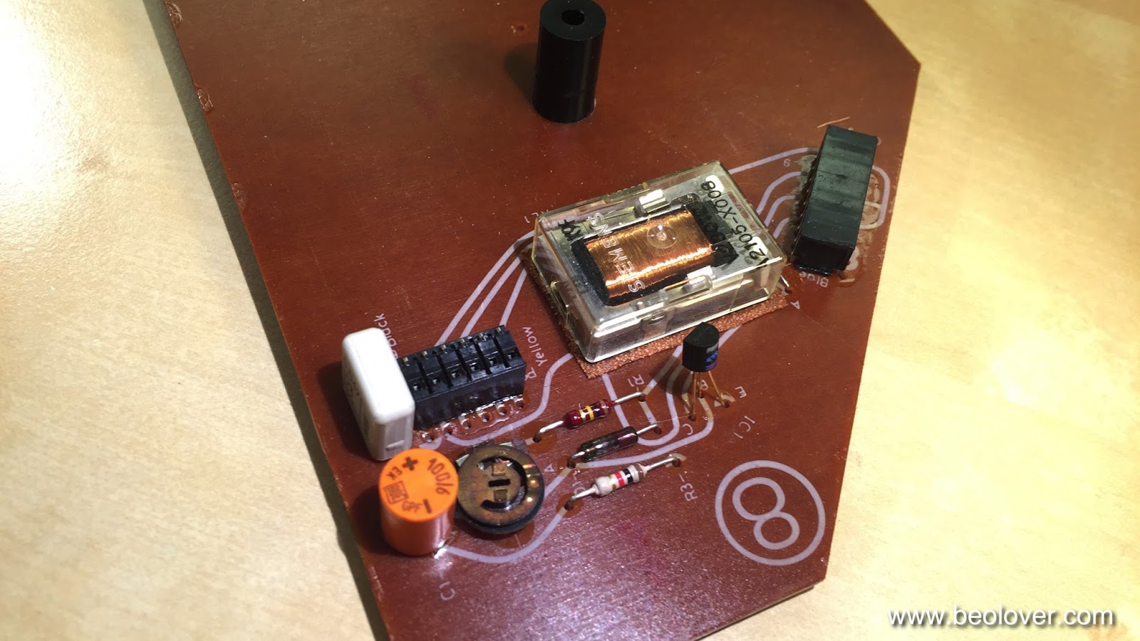
I like to replace the output relay, since they often get stuck on one or both channels as they age. Fortunately, it is the same relay that is used for switching the platter RPM and so my replacement relay boards fit here, too:
These parts are available to other enthusiasts, just send me an email.
This shows the relay and the capacitor replaced:
The red switch allows to connect the system and the signal grounds. This can help if there are hum issues due to improper connections within the amplifier or the cable (usually when RCA adapters are used that do not breakout the system ground).

Before I put the board back in, I also fixed the keypad. It had a loose key stop that caused one of the keys to pop up above the pad surface:
This shows the STOP key from the back with the loose stop:
I glued the stop back on and also reattached the loose pad strips on the sides:
This shows the end result of this repair:
Beautiful! On to adjusting the chassis and the platter.