Featured Post

Beolover SyncDrive: DC Platter Motor Replacement for Beogram 4002 and 4004 (Type 551x and 552x)

Late Beogram 4002 and the 4004 (Types 551x and 552x), which have DC platter motors instead of the earlier synchronous AC motors usually suff...

Showing posts with label 1523RSBG4002. Show all posts

Saturday, April 28, 2018

Beogram 4002 (5513): Final Adjustments, a New Solenoid, and Test Drive with Christoph Spendel & Wolfgang Schlüter Group on MPS

After restoring the DC motor of the Beogram 4002 (5513) that is on my bench right now it was time to finish it up. My customer had not replaced the sensor arm LED, so I did that before doing the final adjustments. This shows the original sensor arm light bulb in its compartment and the LED assembly that I used to replace it:
I removed the bulb and installed the LED. The flexPCB folds into the bulb compartment:
This shows the LED in action:
Then I did the usual adjustments. This shows the adjustment of the tracking feedback.
Then I adjusted the platter height, level and sub-chassis height. The next step was the adjustment of the arm lowering limit, which is the final safeguard against catastrophic tip damage should the record detection mechanism ever fail:
The next step was the calibration of the tracking weight. To ensure a stable calibration, it is a good idea to replace the C-clip that is used to hold the counter weight adjustment screw in place
with a M3 nut and a washer:
This allows fixing the weight position in place permanently top ensure that the calibration is retained during return shipping of the Beogram.
The next step was to calibrate the weight and set the adjustment wheel to reflect the correct weight:
After this was done I realized that the tone arm sometimes would not go back to its parallel position by itself. I investigated and the culprit turned out to be a shifted copper 'slip pad' under the arm level adjustment screw:
I removed the pad and put new adhesive tape on it:
After cutting the excess tape off I glued the pad into its correct place, giving the arm some more lateral freedom to move:
Then it was time to put a record on and play it. Unfortunately, after the needle reached the exit groove, the arm did not lift, dragging the needle across the record surface while the carriage returned to its home position. Not very Beolovely! I investigated the situation. The arm lift appeared to work properly when using the up/down button. After playing a few more records I learned that the problem only occurred after the arm was down for a while, like during play of an entire side. First I thought the arm lowering mechanism had a mechanical problem, and I took everything apart to inspect and lubricate:
After putting everything back together, further tests revealed that this did not rectify the situation. The needle still got dragged across the record! I hooked up a multimeter to the solenoid coil to measure whether the solenoid would be correctly activated during carriage return. My tests revealed that the voltage changed properly at the coil during return, but the solenoid did not release. This left only one culprit: The solenoid itself. I extracted the solenoid from another Beogram (they are all  interchangeable) and implanted it. This shows the original solenoid in place:
And with the new one:
I played another record and indeed this seemed to have fixed the issue! A strange solenoid problem. It did not get hot or show any other signs of distress. It simply got stuck after being activated for a while...anyway, time to move on and celebrate!

I put a good condition MMC20 EN cartridge onto the arm and played a recently acquired record buy the MPS label on: Christoph Spendel and Wolfgang Schlüter Group: September Memories. Another great release by the German MPS label. Especially the title track is wonderful. Perfect for a Beogram test-drive:
I will now play this Beogram 4002 a bit more to ensure that there are no intermittent issues, and then it will be time to send it home!

Monday, April 23, 2018

Beogram 4002 (5513): DC Motor Restoration

After rebuilding the electronics of the Beogram 4002 (5513) that I am working on right now it was time to restore the DC motor. They all need their brass sleeve bearings infused with oil under vacuum. This requires to disassemble the motor. This shows the motor as extracted from the Beogram:
I took it apart:
The bearings are the two small donuts on the black pad. I immersed them into motor oil and pulled a vacuum. Immediately vigorous bubbling started as the air was drawn from the porous Oilite bearing material:
These bearings took more than 48 hours until the bubbling stopped, which signified that the oil content in them bearing material was replenished. I extracted the bearings from the oil
and reassembled the motor. then it was time for a 24 hrs RPM stability test with the BeoloverRPM device, which allows logging the RPM every 10 sec for extended periods of time. This is a great tool for pinpointing intermittent RPM fluctuations, which is very difficult to do otherwise. BeoloverRPM is available to other enthusiasts...just send an email or use the contact form on the right. This shows the BeoloverRPM in action:
After about 24 hrs I was able to make this graph with the logged data:
This is as good as it gets for the DC motor Beograms. The gradual change over time is probably temperature related...a bit of influence by the moon phase may also be part of the equation (just kidding...;-). The joys of analog control systems!


Beogram 4002 (5513): Restoration of the Main PCB and Installation of a Biasing Trimmer for TR3

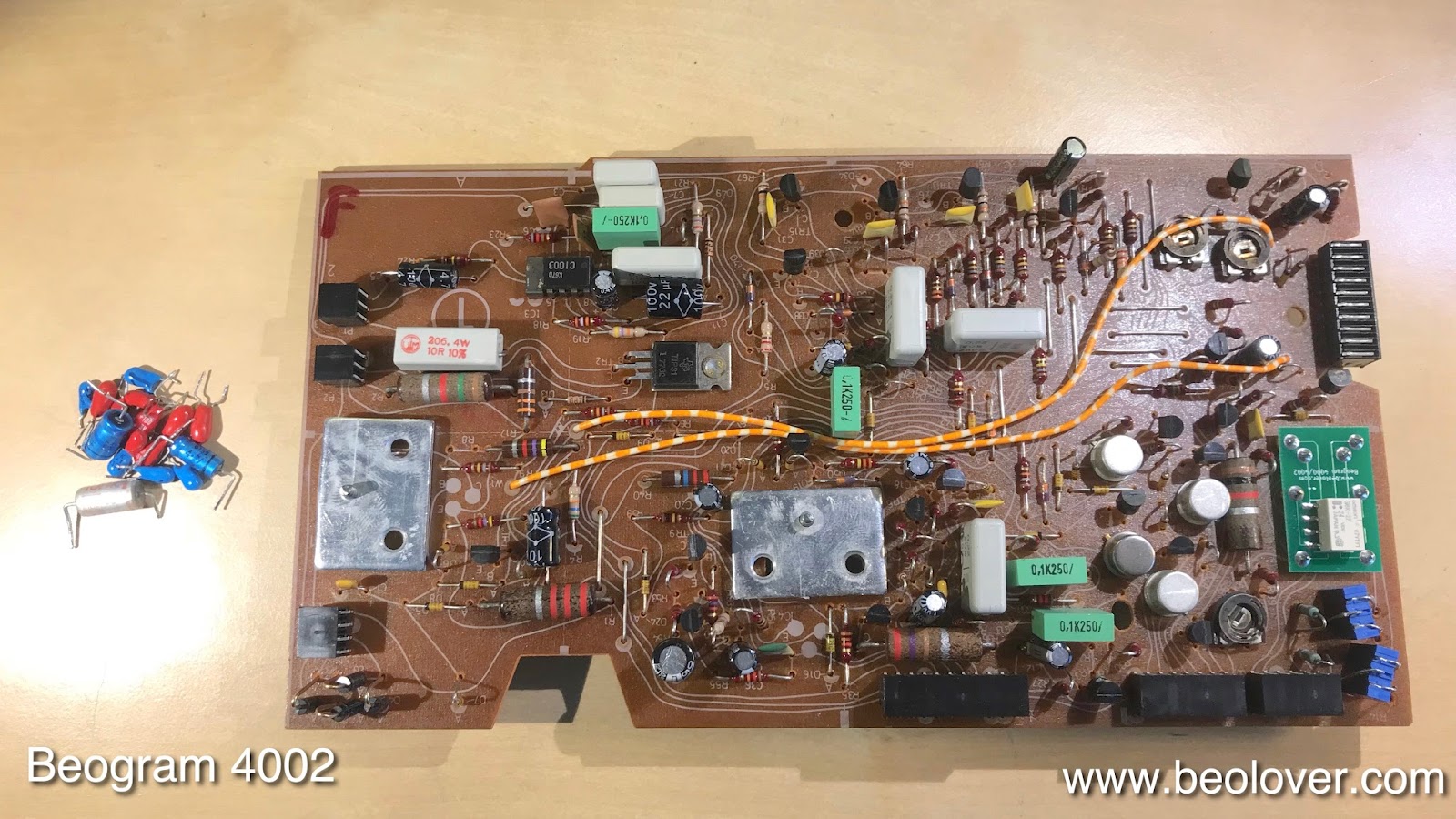
After restoring the basic functionality of the Beogram 4002 (5513) that I am restoring right now, it was time to complete the restoration of the main PCB and install a trimmer to properly bias TR3, which is responsible for the amplification of the record detection sensor signal. This shows the board as I received it:
My customer already had replaced the RPM relay and trimmers. I completed the job by replacing all electrolytic capacitors,
and by installing a trimmer that allows the adjustment of the bias at the base of 
TR3. This shows the trimmer temporarily installed on the backside of the board allowing adjustment while the board was installed/powered up:
Once the collector DC voltage was set to 4.0V, I installed the trimmer on the component side:
The original design has a fixed resistor in place, which in most cases results in too low amplification due to unpredictable variations in the current gain of the transistor placed as TR3. Proper amplification is important to prevent damage to the needle when the deck is accidentally started without a record on the platter.
Once this was done I updated the installation of the replacement reservoir capacitor assembly that also had been installed already:
On to the installation of a LED in the sensor arm...


Friday, April 20, 2018

Beogram 4002 (5513): First Contact and Two Dead Transistors

I recently received a Beogram 4002. The owner already had started working on it, but then decided to send it over for some trouble shooting. This shows the unit:
It is in pretty good condition. The aluminum parts are almost pristine except a few small scratches in the platter. The keypad has the usual wear pattern and some blank spots on the START button. I took out the aluminum panels and had a look:
When I plugged it in and pressed start, the platter motor started running but the carriage would not move at all. Pressing start results in turning on of TR12 whose collector then goes to about 17V. This voltage turns on TR19 in the H-bridge that controls the carriage motor. I checked the presence of the 17V at TR19 when pressing start. The voltage made it there indicating that TR12 was o.k. Then I checked the voltages at TR20 when TR19 was activated. This test showed that TR20 would not turn on. I extracted it from the board and indeed a transistor tester revealed that it was burned out. I replaced the transistor with a new one, put the board back in place and voila, pressing start activated the carriage.

However, after moving about 2-3mm out, it immediately returned to the home position as if STOP was pressed immediately after start. I checked the voltage at the base of TR13, which controls the stop function. The voltage there was consistently 0V, indicating that either something pulled the base down to 0V or that TR13 itself had a problem. First I checked the start and end switchers, which can pull the base down, but both switches worked properly. Then I extracted TR13 and the transistor tester showed it to be damaged. I replaced it with a new transistor and then everything worked. Pressing start launched the carriage and it found the set down point for LPs and the arm lowered. Then it started racing towards the center of the platter, indicating that the tracking feedback needed some adjusting. Here is a picture of the two extracted transistors:
This Beogram is on the way to recovery!