Featured Post

Beolover SyncDrive: DC Platter Motor Replacement for Beogram 4002 and 4004 (Type 551x and 552x)

Late Beogram 4002 and the 4004 (Types 551x and 552x), which have DC platter motors instead of the earlier synchronous AC motors usually suff...

Showing posts with label transistor. Show all posts

Saturday, February 5, 2022

Beogram 4004 (5526): Return to Bench with Blown Fuse - Replacement of Solenoid Transistor

A Beogram 4004 (5526) that I restored in April 2019 just returned to my bench with blown fuses. I was told that "it died as I was lowering the tone arm and is now totally non-responsive".

This suggested an issue with 1IC4, the Darlington transistor that is responsible for regulating the current through the arm lowering solenoid. This solenoid is the largest current 'hog' of the Beogram and puts quite a bit of strain on this IC whenever the solenoid is activated.

But first I installed two tabs on the power entry plug for convenient connection of a bench supply for testing the board:

Then I extracted the TIP125 that was installed as 1IC4 and plugged it into my transistor tester. It gave me a strange reading with an additional forward direction diode between emitter and collector, while still showing a reasonable turn-on voltage of 1.09V for a Darlington.
I think this shows the limitations of transistor testers...the new TIP107 replacement showed a normal reading:

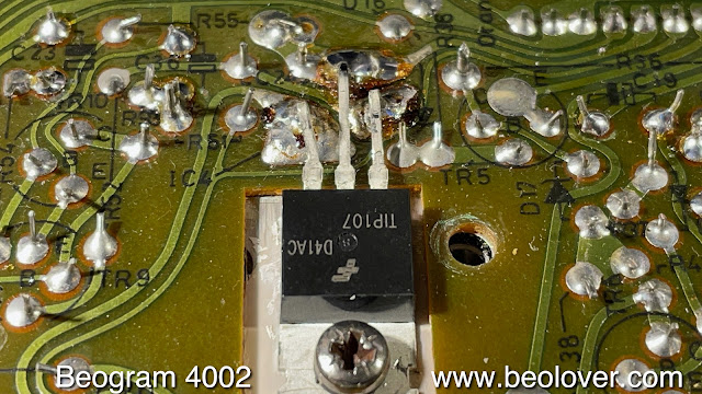
I installed it 
and tested the deck with the bench supply providing power. All went normal and the arm dropped normally at the LP run in groove position.
I decided to also replace the other two power transistors that run the platter motor (1TR2) 
and the 24V rail of the Beogram (1IC1)
with a TIP120 and a TIP31, respectively, to be on the safe side.
I stuck a cartridge on the arm and put a record on the platter (Eberhard Weber Colours "Little Movements"  (ECM 1-1186), and it played as it should. So I think this Beogram may be fixed. I will give it some more play and then it will be time for it to return to its owner!


Thursday, December 26, 2019

Beogram 8000: A Fun Evening With the Record Detection Circuit (the Conclusion)

This is a follow up to this post. After I made the post about the failed transistors in the record detection circuit of a Beogram 8000, I received this forwarded input from the owner of the 8000 who has a friend who understands circuits:

“I think he [the Beolover] replaced every transistor he came across until he got to tr16.  Then he measured it, it was OK, so he didn’t replace it.  I think he should replace TR16.  The reason is TR16 operates with 6 ua of base current, maybe his curve tracer is a different current.  Clearly he has the right waveform going into TR16, and noise is still coming out.  With the beta he measured this should not be happening, so something is wrong with the measurement.  This thing where all the transistors wear out is disturbing.  Of course this circuit calls for very high beta in every stage, but it shows us how transient our technology is.  A transistor is only a transistor because of the sandwich of 3 different types of impurities, which we know move around. After 40 years, it seems they move around a lot.  Clearly these parts worked at one time, but they all changed enough to stop working.  It’s rare to see something this old with good enough documentation and people willing to keep it going.”

Point taken. I also wondered why this circuit was still not working properly even with TR16 measuring o.k., and I have no idea what exactly my little transistor tester does in terms of applied voltages etc...when it does its magic.
Only one way to find out: I restored R72 to 1M and put R70 back into the circuit, and then replaced TR16 with a 2N2222 that yielded an hfE of 225 on my transistor tester. It still did not detect the absence of a record. So I rummaged through my parts collection and finally found a new BC547B that yielded an hfE of 430, and put it into the circuit, and that fixed it:
The yellow trace is the measurement point between R72 and R71, and the green trace is HH (collector of TR16). This qualifies as a good logic LOW, and the micro controller apparently thought so, too. It swept the arms across the platter in search of smaller records, and then returned home and turned off, as it should!

So the conclusion is, yes, the circuit can work as designed (indeed, a satisfying result!...;-)

One question remains: Why does TR16 need such a high hfE? Sure, the base current is pretty low due to the 1M resistor. In this particular case, the minimum voltage in the sawtooth at R71/72 is about 6V, i.e. the minimum base current into TR16 should be about 5.3uA. The current across CE should be limited to 5V/33kOhm=151uA if the transistor is fully on. That is only about a factor 28, i.e. a hfE of 225 should be plenty to pull the collector of TR16 down with 5.3uA.
This got me motivated to look a bit deeper into measuring hfE values. It turns out they are strongly collector current dependent. This figure is taken from the BC547B datasheet provided by ONsemi:
So we see that at the low 151uA current that TR16 sees, the current gain is only about 60% of the maximum value at about 20mA. The 2N2222 has a similar curve (see here), and that (together with the strong variation of hfE values in general between individual transistors of the same series) may explain why the 2N2222 was not able to perform properly in this circuit. 


Tuesday, December 24, 2019

Beogram 8000: A Fun Evening With the Record Detection Circuit

*************************This post has a follow-up. Please, see here*****************************

I recently started working on a Beogram 8000 from California. As the usual, as a first step, I replaced the electrolytic capacitors and the motor AC cap in the power block, then re-flowed the solder points of the headers, after which it was time to give the unit a first try. I pressed start and the carriage started moving, and without a record on the platter the unit activated the tonearm lift at the LP setdown point. Not what it was supposed to do. I concluded there was an issue with the record detection circuit. 
This is the relevant part of the Beogram 8000 circuit diagram:


I should point out that the Beogram 8000 featured here did not have the trimmer R64 at the sensor input, i.e. is one of the earlier models.
The first spot to check is the collector of TR14, which amplifies the signal of the sensor 5PH1 as the platter ribs pass through under the sensor arm. I drove the arm manually further onto the platter to get a stable signal, and then put the oscilloscope probe to the collector. This is the signal I measured:
The dips correspond to the ribs passing under the sensor and blocking the light reflection. Unfortunately, there is no prescribed wave form in the manual, but judging from the very similar circuit in the 4002/4 models this signal was way too low.
the next step was to measure the sensor signal directly at C15, which yielded about the waveform shown in the manual:
Therefore, I suspected that TR14 had a too low gain (hfE), which is often encountered in the Beogram 4002/4 models. I extracted and measured it:
It only showed with a gain of 94, which is well below the minimum gain of 200 specified for the BC547B. I replaced it with a 2N2222 that demonstrated a gain of 215, and measured again:
Much better. The dips go to zero and the amplitude is almost 10V. Unfortunately, there is no spec in the manual for this measurement, but judging from the 4002s the above qualifies as a decent signal. I hoped at this point this would fix the issue. But no cigar. The Beogram again dropped the arm at the LP setdown point in absence of a record. 
If the sensor signal is good, then the next measurement spot is at the junction between R71 and R72. I got the yellow curve in the screen below:
The triangles peak at about 7V and dip down to about 3V, in contrast to the specified 10-to-7V drop shown in the manual. This means there is a too small voltage at the base of TR16, which may mean trouble pulling the 'Disc Detector' signal (HH) properly to a logic LOW state below 0.2V.
I measured HH and that is the green curve in the graph above. At this point I though, bingo, there must also be an issue with TR15 that does the tugging at the base of TR16. I extracted it for measurement:
It came up with an hfE of 158, which is also a bit low. I replaced it with a new BC557B with an hfE of 275, above the minimum 200 spec. So far so good. I measured again at R71/72 and now the curve was according to specification:
Unfortunately, record detection still did not work, and the green curve was a bit better, but the spikes, while a bit weaker, were still present. Ok, I thought, TR16 must also be out of spec. I measured:
...and got a happy hfE of 434 (it is normal that the hfE varies a lot, and all is good as long as it is above its minimum spec, at least for most circuits.
To make sure that the chain of command was intact between TR16 and the micro controller input I grounded the collector of TR16, which should permanently disable record detection, and it should always behave as if there were no record. I pressed Play, and indeed, the arms ran across the platter in search of a smaller record, and then turned around and went back home. So that was working.
At this point I was a bit at a loss. For some reason, the pull at the base of TR16 was not strong enough, and it did not fully turn on. A mystery!
I decided to play a bit with the circuit and I replaced R72 with a 100k resistor, increasing the current by a factor 10 into the base of TR16 (or so I thought). This did not fix the issue. It turns out that the higher current was depleting C19 too quickly, reducing its voltage too fast between the passing of the platter ribs, again causing spikes in HH. This meant I needed to increase the current into C19 also, which was easily done by removing R70, which partially drains the collector of TR15 away from C19. After eliminating R70 from the circuit, it started working properly with HH going fully to zero when the ribs were visible to the sensor:
Luckily, HH also quickly restored itself to 5V when covering the sensor (simulating a record), i.e. the record detection mechanism of this Beogram 8000 is doing what it is supposed to be doing.
At this point, I am not fully satisfied with this result since I do not fully understand what is going on. I guess another 8000 where this circuit works 'as is' will need to show me the light some other day. The B&O excitement just never ends!...;-)




Friday, April 20, 2018

Beogram 4002 (5513): First Contact and Two Dead Transistors

I recently received a Beogram 4002. The owner already had started working on it, but then decided to send it over for some trouble shooting. This shows the unit:
It is in pretty good condition. The aluminum parts are almost pristine except a few small scratches in the platter. The keypad has the usual wear pattern and some blank spots on the START button. I took out the aluminum panels and had a look:
When I plugged it in and pressed start, the platter motor started running but the carriage would not move at all. Pressing start results in turning on of TR12 whose collector then goes to about 17V. This voltage turns on TR19 in the H-bridge that controls the carriage motor. I checked the presence of the 17V at TR19 when pressing start. The voltage made it there indicating that TR12 was o.k. Then I checked the voltages at TR20 when TR19 was activated. This test showed that TR20 would not turn on. I extracted it from the board and indeed a transistor tester revealed that it was burned out. I replaced the transistor with a new one, put the board back in place and voila, pressing start activated the carriage.

However, after moving about 2-3mm out, it immediately returned to the home position as if STOP was pressed immediately after start. I checked the voltage at the base of TR13, which controls the stop function. The voltage there was consistently 0V, indicating that either something pulled the base down to 0V or that TR13 itself had a problem. First I checked the start and end switchers, which can pull the base down, but both switches worked properly. Then I extracted TR13 and the transistor tester showed it to be damaged. I replaced it with a new transistor and then everything worked. Pressing start launched the carriage and it found the set down point for LPs and the arm lowered. Then it started racing towards the center of the platter, indicating that the tracking feedback needed some adjusting. Here is a picture of the two extracted transistors:
This Beogram is on the way to recovery!


Tuesday, February 20, 2018

Beomaster 8000: Left Channel Output Amplifier DC Offset Resolved

This Beomaster 8000 is almost fully functional. Actually it does function and play music but it doesn't completely pass the service manual DC Offset adjustment procedure. It is very close but no cigar.

The right channel adjusts perfectly. With the Beomaster on and warmed up I have the right channel output amplifier adjusted so the DC Offset measures 0.0V ± 0.1mV.

The left channel could only be adjusted to around 0.040V (40mV). Here is the differential amplifier circuit where this adjustment is made.


The adjustment trimmer (R200) adjusts the current to even out the differences in hFE between TR201 and TR202 (BC546B NPN transistors). As I said, the left channel cannot be adjusted to the 0.0V ± 5mV range specified by the Beomaster 8000 service manual.


I pulled out TR201 and TR202 to measure them with my transistor tester. Sure enough, their hFE measured quite a bit different. TR201 measures 146 and TR202 measures 318.


I checked a few other BC546B transistors and they are all close to hFE = 300. So TR201 appears to be the culprit. I went ahead and replaced both TR201 and TR202 with BC546B transistors as close of an hFE match as I could find.

That did it. I rechecked the no-load current adjustment first then performed the DC Offset adjustment. Now I can get the left channel output amplifier down to a good DC Offset value.


This Beomaster is feeling like it is into the home stretch now. Time to start closing up the cabinet and doing some real play testing.

Tuesday, April 29, 2014

Beomaster 6000 4-Channel: Output Amplifier Repair and Quiescent Current Adjustment

Well...I did something really stupid. It seems like a repeat of history. I got into this beoloving thing due to a smoking Beomaster 8000, and now I fried one of the four output amplifiers (RR) of the Beomaster 6000 4-Channel!! Exciting! Very!

Here is what happened: I used an only partially insulated screwdriver to adjust the quiescent (quiet) current of the output stages, and when I got to the rear right channel, I slipped with the screwdriver out of the (bent down) trimmer and I very briefly touched the exposed lead of the resistor to the left of it (i.e. 11R96). At the same time, I touched the metal U-shape that holds the output printed circuit board with the upper, non-isolated part of the screwdriver (this is definitely a good moment considering buying a set of electrician screwdrivers...;-). A brief spark at the resistor, and the formerly 7.2 mV across the collector resistor of the PNP Darlington in the output turned into about 150mV, followed by a rapid heating of the respective heat sink (and a dramatic raise in my pulse plus developing sweat...;-). However, the main fuse of the Beomaster did not blow. If you think of it, the 150 mV across 0.12 Ohms correspond to less  than 2 Amps, i.e. this makes somewhat sense. At that point I did not understand why there was so little current, despite both output transistors having been fried (as it turned out when putting the Ohm meter to them via the access granted through the heat sink ribs). Later it became clear that I also fried the emitter resistor of the npn Darlington (11R102)
Oh well, after the initial panic subsided, I discovered that it is actually not too difficult to fix an output stage of the Beomaster 6000 4-Channel, despite the relatively poor service friendliness of the 'everything soldered together' design of this early 1970's construction.
I was not able to find the matched pair of MJ2501 (pnp) and MJ3001 (npn) Darlingtons...it seems they only kept the MJ3001 on the active device list, but dropped the pnp version. Since it is best to use matched pairs in push-pull amps, I decided to use the MJ11015 (pnp) and MJ11016 (npn) pair, which are slightly beefier versions available in the same TO-3 package and with the same DC current gain values. I also replaced the driver for the output, 11TR8 (a BC332, also not available anymore), with a 2N2222A with similar characteristics due to the possibility that this transistor was exposed to maximum rating-approaching voltage levels. On a general note, due to the feedback based design, it is not very crucial what transistors are used as long as they can take power and voltage, are fast enough and have sufficient current gain.

I made a video about the repair procedure:

 Here are a few high res pictures of the process:

After removing the two screws that hold the transistors in place the heat sinks can be pushed a bit back and then upwards to reveal access to the transistors.


Moto MJ3001 and MJ2501 say hello after their extraction...can one make cuff links from them??


Here is a picture of the pulled circuit board to allow access to the amplifier circuit for replacing the two output resistors. If you do this, do it slowly and deliberately making sure that the wires are all free to move... The right red 'can' on the bottom (hidden underneath the wires) was the resistor that went open circuit (and prevented the fuse from burning by limiting the total current to below 2 A after the transistors died):


Here is a shot of the old and new resistors (Newark 73M8331, 0.12 Ohm, 3W). I decided to replace both of them to make sure there would be no later surprises:


Here is a shot of the amplifier after replacing the resistors and also the electrolytic caps with 105C models (I did that for all four outputs - I also measured the capacitance and ESR for all the extracted caps for the fun of it: not one was out of spec!):


This is how I adjusted the quiescent (quiet) current (shown for the left rear output). It is convenient to simply clip the probes to the emitter leads of the Darlingtons. This measures the voltage across both output resistors (in this case 11R48 and 11R49), i.e on needs to adjust for 2x 7.2mV = 14.4 mV (now, please, do me a favor: use an insulated screwdriver...and put some cardboard sheathing into the U-profile to prevent accidental contact between circuit and ground!...;-):


That's it! Back to the actual restoration tasks!