Featured Post

Beolover SyncDrive: DC Platter Motor Replacement for Beogram 4002 and 4004 (Type 551x and 552x)

Late Beogram 4002 and the 4004 (Types 551x and 552x), which have DC platter motors instead of the earlier synchronous AC motors usually suff...

Showing posts with label darlington. Show all posts

Friday, May 3, 2024

Beogram 4002: Restoration of Short Circuited Solenoid Coil and Repair of Main PCB

I recently received the short circuited solenoid coil from a DC motor Beogram 4002 together with the main PCB from a customer in Texas. I asked for sending the PCB along since there is usually a reason when solenoid coils burn out. And in the later DC motor 4002 and 4004s this reason is usually to be found on the main PCB.

This shows the components as received:

First, I measured the coil to confirm my customer's diagnosis:
Indeed, the resistance was much too low at 1.6 Ohm. A good coil usually shows about 9 Ohm.
To my surprise this coil assembly looked a bit different from those I restored so far. The 'normal' coil assembly (left) has a locking washer that holds the tube inside the coil in place:
In contrast, the present assembly (right, already with the plunger removed) seemed to have been assembled using a press fit. This shows the back end of the assemblies (the present one is on the right in this picture). Also a bit different.
Since I was not able to see from the front end how the tube was exactly mounted, I decided to try removing the coil while the assembly was still together. I hoped this would give me some more clarity how to disassemble everything.  Since it is impossible to unwind the coil with the assembly together, I used a Dremel with a cutting wheel to cut into it:
With a bit of 'measured violence' I was able to get most of the coil windings off:
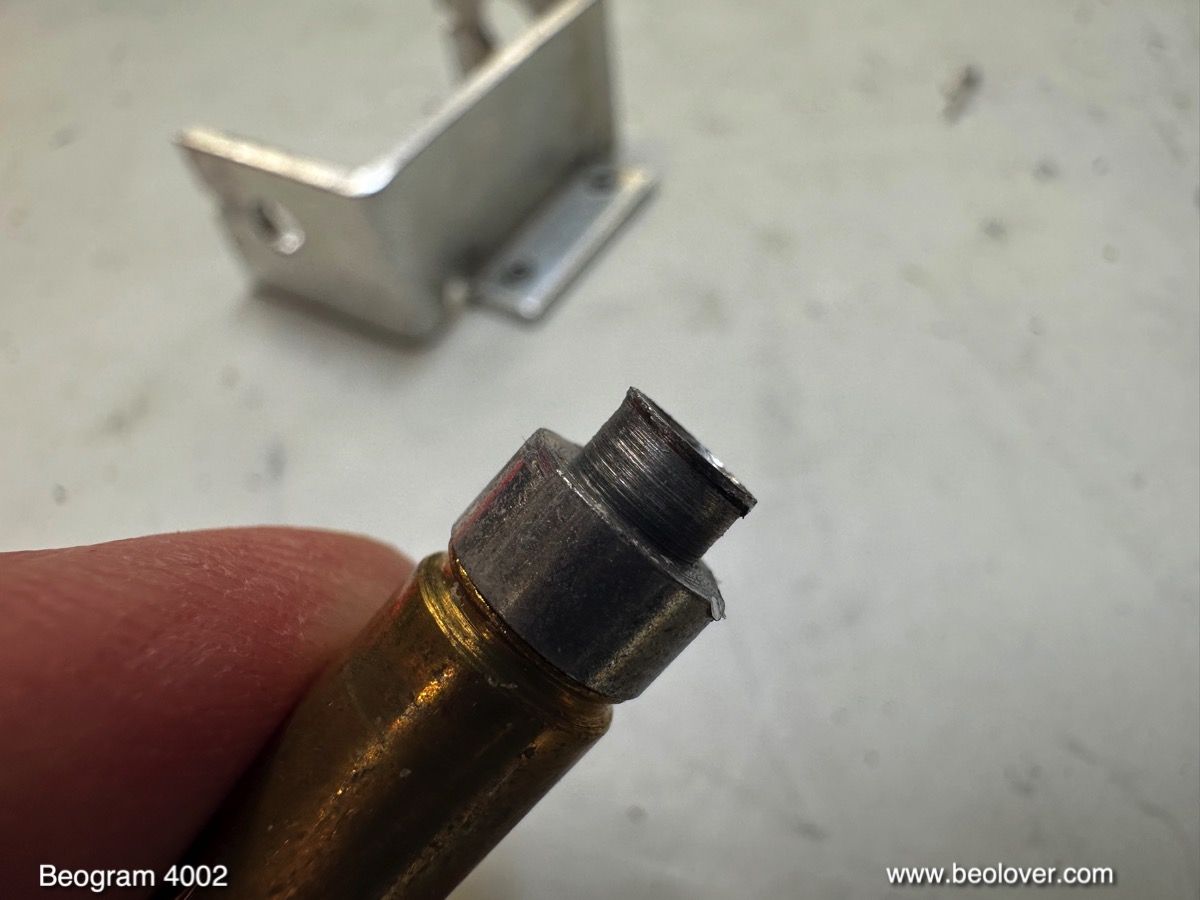
With most of the coil gone I was able to see that it is possible to press the tube out with an arbor press. this shows the liberated parts:
The tube was basically riveted into the orifice in the mounting bracket:
Next time I will probably use a drill to remove the front end of the pressed-in tube before using the arbor press. I installed a new coil made with a 3D printed plastic core:
If you need one, my replacement coils are available via the Beolover Store.
I installed the rebuilt coil assembly into my bench 4002:
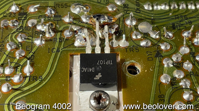
I also put in the main PCB that came along with it. Then I plugged my Beogram in, and immediately the coil activated. I quickly unplugged the unit before the coil had a chance to get hot. This behavior suggested a burned through 1IC4, which controls the solenoid current:
I removed the original TIP125 Darlington and replaced it with a stronger TIP107, hoping it will last a bit longer:
This fixed the issue and the Beogram operated normally by lowering the arm at the LP setdown point:


My experience is that most Beogram 4002 and 4004 have issues with their power transistors and I usually replace all of them preventatively when I restore one of these vintage beauties. 
At any rate, this main PCB is again able to control the solenoid! It is time to send everything back to Texas!


Saturday, February 5, 2022

Beogram 4004 (5526): Return to Bench with Blown Fuse - Replacement of Solenoid Transistor

A Beogram 4004 (5526) that I restored in April 2019 just returned to my bench with blown fuses. I was told that "it died as I was lowering the tone arm and is now totally non-responsive".

This suggested an issue with 1IC4, the Darlington transistor that is responsible for regulating the current through the arm lowering solenoid. This solenoid is the largest current 'hog' of the Beogram and puts quite a bit of strain on this IC whenever the solenoid is activated.

But first I installed two tabs on the power entry plug for convenient connection of a bench supply for testing the board:

Then I extracted the TIP125 that was installed as 1IC4 and plugged it into my transistor tester. It gave me a strange reading with an additional forward direction diode between emitter and collector, while still showing a reasonable turn-on voltage of 1.09V for a Darlington.
I think this shows the limitations of transistor testers...the new TIP107 replacement showed a normal reading:

I installed it 
and tested the deck with the bench supply providing power. All went normal and the arm dropped normally at the LP run in groove position.
I decided to also replace the other two power transistors that run the platter motor (1TR2) 
and the 24V rail of the Beogram (1IC1)
with a TIP120 and a TIP31, respectively, to be on the safe side.
I stuck a cartridge on the arm and put a record on the platter (Eberhard Weber Colours "Little Movements"  (ECM 1-1186), and it played as it should. So I think this Beogram may be fixed. I will give it some more play and then it will be time for it to return to its owner!


Tuesday, January 30, 2018

Beomaster 6000 (2702) restoration: re-assembling the output subframe

Before putting the output stage PCB back into the subframe there are a few things to take care of. First is cleaning the frame, the heat sinks and the plastic spacers. To remove the glue on the frame I used paint remover followed by some alcohol cleaner and water with detergent. I looks almost as new again!


And after the cleaning...


The warping of the output PCB has been mentioned a few times already and to avoid the common short circuits between the subframe and the solder side of the PCB I decided to use a permanent shielding in between. I used a sheet of 1mm thick plastic that I cut to size and glued on the inside of the subframe. Several cut-outs need to be done off course to fit everything back later and to give the wires, screws, etc. the space they need.


When I mounted the PCB I noticed something interesting:  the warping of the PCB was almost completely gone. The reason is simple: the many wires that come from the 8 darlingtons transistors are longer than needed (to allow removal without desoldering) and are "stored" on the bottom of the subframe when everything is mounted. This cable tree however pushes against the board and makes it warp. There are tiny slots on the bottom of the frame (see picture above) that are supposed to hold the board in place. But they are to small and the board jumps out easily. As a precaution (probably not really needed) I glued a small plastic spacer on the board in order to keep the correct distance between board and frame. Again, probably not needed but it helps to get a perfectly aligned and straight board and that looks nice!


Up to the the heat sinks and the output darlington transistors. To make mounting easier and avoid breaking of,  I replaced all the hard wires going the 8 darlingtons and the 4 transistors (that are also mounted on the heat sinks) with flexible wires. AWG 20 (0,5mm²) for the power darlingtons and AWG 24 (0,2mm²) for the other transistors. I tried to respect the original color code and was able to keep all but one original color. Note that the wires all have different lengths !


The mica isolators that are typically used are replaced with sil(icone)-pads. Some of the originals ones where cracked anyhow as you can see in the picture below. I know there is some debate about the pro's and con's of both. Some people stick to mica and use the needed thermal paste. Other swear to silpads. I'm in favour of the latter. It's easier and less messy since you don't need the white thermal paste anymore. I agree that one needs to be careful. These silpads can be punctured if something  (like a tiny ball of solder) sticks between the transistor and frame (heat sink). Therefore it is wise to check the surface smoothness of the transistor (usually the collector connection) and the frame. Also, do not over-tighten the bolts or screws. 


The plastic spacers are fixed to the subframe with a dot of glue, just enough to keep them in place.


The small driver transistors that are used for feedback of temperature and thus allow thermal stability of the power stage (the bias current) do need a bit of thermal paste since they are to small for silpads. One of them was fried on the right output channel and I replaced it with a authorised replacement (MPSA13).


Now all the heatsinks and transistors are mounted on the subframe.


Before moving on to the next phase, I checked a few things to make sure that there was no shortcircuit anywhere, that I had not mixed up the NPN & PNP darlingtons, etc. I found a fault in (again) the front right channel. Something was not measuring correctly. So I had to remove the board again and found a burned resistor 11R69 of 330 ohm that I had not noticed before.  This resistor is in series with the trimmer that regulates the bias current. I did replace all the trimmers before but never checked them for burning out. I did now, and one off course was burned out. Normal, since the driver transistor O1C6 was short circuit on all tree connections!

should be "resistor" of course and not "transisitor"

Checked again and so far so good. But no power yet applied to the board. That's for later.....

Friday, May 2, 2014

Beomaster 6000 4-Channel: Trimmer Replacement in Output Stages

Following excellent advice from Jacques ('charz') at Beoworld.com, I decided to also replace the quiescent current trimmers with modern 25-turn types. The challenge is to mount them in a way to achieve 'trimmability' with the output board installed in its operational position. Luckily the space between the two big 100n capacitors (C1/2 in the LF channel)is perfectly dimensioned to take standard encapsulated trimmer. The only thing left was to extend the leads to be able to bend them in the right orientation to be able to replace the old single turn trimmer. Here is a pic of a new trimmer in comparison with the old after this procedure:


It is important to orient the trimmer in a way that the quiescent current adjustment is in the same orientation as specified in the manual, i.e. current increases in clockwise direction. Otherwise, there might be confusion and hot heatsinks the next time this is done (in another 40 years??...;-). So I made sure that a complete counter clockwise adjustment means zero resistance between the left and center leads (in the orientation shown in the photo).

By the way: I used 500 Ohm trimmers since I was not able to get multi-turn precision 250 Ohm types through my usual channels in the US...I could only find single turn types...so I decided to use 500 Ohm. A look at the circuit diagram shows that there is nothing to worry about this. The only impact is that the base of 11IC3 (LF channel) can be pulled up a bit harder relative to the emitter if one would turn the pot all the way to the high current end due to the larger drop along the trimmer...but this is nothing one would do when following the quiescent current adjustment instructions in the manual (turn all the way CCW then turn on and slowly go CW until desired current is obtained). The 500 Ohm value does not affect the gain of 11TR2 either, since the collector resistor of 11TR2 is provided via 11R10 and 11R16, and the gain is theoretically close to infinite anyway due to the lack of an emitter resistor...Furthermore, the DC network for the base of 11IC3 is 'locked in place' (voltage wise) by the drop across 11IC3, which is defined by the quiescent current adjustment to the specified value, i.e. should be the same no matter if there is a 250 or 500 Ohm trimmer...

Next step was pulling the circuit board out again...certainly not a procedure I like to do. I hope this was the last time!
Here is a pic of the RR channel with new trimmer:

Pretty, how it fits! As if Jacob and his friends knew that I would want to do this in 2014!..;-)
And here a shot of the other three outputs:


And finally: The old 250 Ohm trimmers (which are all in pretty good condition..):


A test of the amplifier with the tuner revealed happy operation. This hopefully concludes the output amplifier restoration!

Tuesday, April 29, 2014

Beomaster 6000 4-Channel: Output Amplifier Repair and Quiescent Current Adjustment

Well...I did something really stupid. It seems like a repeat of history. I got into this beoloving thing due to a smoking Beomaster 8000, and now I fried one of the four output amplifiers (RR) of the Beomaster 6000 4-Channel!! Exciting! Very!

Here is what happened: I used an only partially insulated screwdriver to adjust the quiescent (quiet) current of the output stages, and when I got to the rear right channel, I slipped with the screwdriver out of the (bent down) trimmer and I very briefly touched the exposed lead of the resistor to the left of it (i.e. 11R96). At the same time, I touched the metal U-shape that holds the output printed circuit board with the upper, non-isolated part of the screwdriver (this is definitely a good moment considering buying a set of electrician screwdrivers...;-). A brief spark at the resistor, and the formerly 7.2 mV across the collector resistor of the PNP Darlington in the output turned into about 150mV, followed by a rapid heating of the respective heat sink (and a dramatic raise in my pulse plus developing sweat...;-). However, the main fuse of the Beomaster did not blow. If you think of it, the 150 mV across 0.12 Ohms correspond to less  than 2 Amps, i.e. this makes somewhat sense. At that point I did not understand why there was so little current, despite both output transistors having been fried (as it turned out when putting the Ohm meter to them via the access granted through the heat sink ribs). Later it became clear that I also fried the emitter resistor of the npn Darlington (11R102)
Oh well, after the initial panic subsided, I discovered that it is actually not too difficult to fix an output stage of the Beomaster 6000 4-Channel, despite the relatively poor service friendliness of the 'everything soldered together' design of this early 1970's construction.
I was not able to find the matched pair of MJ2501 (pnp) and MJ3001 (npn) Darlingtons...it seems they only kept the MJ3001 on the active device list, but dropped the pnp version. Since it is best to use matched pairs in push-pull amps, I decided to use the MJ11015 (pnp) and MJ11016 (npn) pair, which are slightly beefier versions available in the same TO-3 package and with the same DC current gain values. I also replaced the driver for the output, 11TR8 (a BC332, also not available anymore), with a 2N2222A with similar characteristics due to the possibility that this transistor was exposed to maximum rating-approaching voltage levels. On a general note, due to the feedback based design, it is not very crucial what transistors are used as long as they can take power and voltage, are fast enough and have sufficient current gain.

I made a video about the repair procedure:

 Here are a few high res pictures of the process:

After removing the two screws that hold the transistors in place the heat sinks can be pushed a bit back and then upwards to reveal access to the transistors.


Moto MJ3001 and MJ2501 say hello after their extraction...can one make cuff links from them??


Here is a picture of the pulled circuit board to allow access to the amplifier circuit for replacing the two output resistors. If you do this, do it slowly and deliberately making sure that the wires are all free to move... The right red 'can' on the bottom (hidden underneath the wires) was the resistor that went open circuit (and prevented the fuse from burning by limiting the total current to below 2 A after the transistors died):


Here is a shot of the old and new resistors (Newark 73M8331, 0.12 Ohm, 3W). I decided to replace both of them to make sure there would be no later surprises:


Here is a shot of the amplifier after replacing the resistors and also the electrolytic caps with 105C models (I did that for all four outputs - I also measured the capacitance and ESR for all the extracted caps for the fun of it: not one was out of spec!):


This is how I adjusted the quiescent (quiet) current (shown for the left rear output). It is convenient to simply clip the probes to the emitter leads of the Darlingtons. This measures the voltage across both output resistors (in this case 11R48 and 11R49), i.e on needs to adjust for 2x 7.2mV = 14.4 mV (now, please, do me a favor: use an insulated screwdriver...and put some cardboard sheathing into the U-profile to prevent accidental contact between circuit and ground!...;-):


That's it! Back to the actual restoration tasks!