Featured Post

Beolover SyncDrive: DC Platter Motor Replacement for Beogram 4002 and 4004 (Type 551x and 552x)

Late Beogram 4002 and the 4004 (Types 551x and 552x), which have DC platter motors instead of the earlier synchronous AC motors usually suff...

Showing posts with label 2702. Show all posts

Sunday, April 8, 2018

Beomaster 6000 (2702) restoration: checking, power-up and calibration

Everything is back into the chassis and now it's time to do a last check of all the wiring and powering up. It's important to make sure that no wires have been cracked, became loose or touching the chassis. This may seems obvious, but it is so important in a Beomaster 6000 quad because the space is so tight and most wiring is done with hard wires. I took all the time that I needed and found one wire broken off: a ground connection to the pre-amp.

So, a last peek inside before powering up......


I plugged the unit into my Variac transformer, gently raised the voltage to the required 230V and...........it fired up on all engines! I selected a FM station and listened to Katie Melua's version of Louis Armstrongs "What a wonderful world" ! And indeed it was......

That was a big relief. You never know what will happen after such a big restoration. But, off course, I had tested everything already before putting it al in the main chassis (check here). 

Some final calibration was now needed. I started with the power supply. I had done this before when restoring the power supply PCB, but under load settings may change. I found some slight variation. The +18V had now dropped to +17,85. Not to bad. And the -5V was now -5,1V (not sure why it went up). With the new trimmers in place, it was easy to recalibrate to the correct voltages.


On the same power supply PCB, a trimmer is located to balance the FM reception lights.

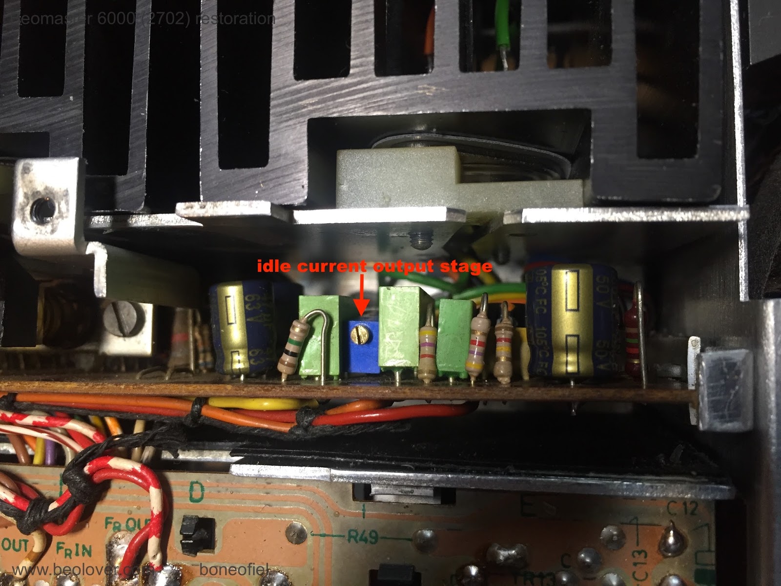
The idle (quiescent, bias or no-signal) current was already set before, but I checked it again by measuring the voltage drop over the 2 emitter transistors (0,12 ohm), in series, that are in each set of the Darlington output stages. The service manual describes to measure directly on one of the collector resistors on the PCB. They are very difficult (if not impossible) to reach once the PCB is in place in the subframe. The easiest way is to measure directly on the emitter contacts of both Darlington transistors (PNP and NPN pair) on the cooling elements (white & green wires in below picture). The correct setting in this case is 14,4mV (2x7,2mV). The extra base-emitter current that flows through the emitter resistors together with the collector-emitter current, is neglectable.


Next was the FM bottom voltage adjustment. The manual describes +4,5V. The FM tuner is driven by a variable DC voltage and to make sure that lowest FM frequency is correct and corresponds with the display, this bottom voltage needs to be set correctly.


Another series of adjustment are related to the FM display board with the signal strength meter, the stereo light and the tuning balance lights.


Other calibrations (like the ultrasonic receiver and the Commander remote) have been done before (see here).

Up next is the mounting of the FM display scale and fixing a new dial cord.

Thursday, February 22, 2018

Beomaster 6000 (2702) restoration: finishing re-assembling without chassis + testing

All the PCB's have been reconnected and time to check if all is working. I know, it looks a bit messy, but at least I got it all together on my piece of wood. I checked and rechecked all the wiring, looked for possible short-circuits, etc. 


Let's see if we can bring this mess to life ! Plugged it into my variac and slowly brought up the power. I saw lights coming on.........and the power relay kicking in. Yes !!!! No smoke or bad smell either :-)


I was a  happy man, but not for long sadly enough........Two major events happened. The first one: I could not select anything. The volume/tone/balance control was working. Motor and clutches running. I also did not get any bias current on the output stages (I had connected my multimeter before powering up to check). Hmmm.. No 60V DC rail either. I had checked the power supply before and all was working fine with the correct voltages. The 20V and 21,5V DC for the electronic switch are derived from the 60V DC, so that is why the switch is not working and no selection can be made (FM presets and input selection). Turned out the power relay did not make good contact to bring the 60V DC to the PCB's! The other voltages from the power supply PCB (18V DC, -5V DC and 180V DC) are not going through the power relay. I took the relay out and cleaned the contacts (again). But then decided to put in a spare relay that I knew was working fine. Powered up again and YES, not only lights but also switch board working and bias current. Measured over the output darlington emitter resistors and got about 4mV. Should be 14.4mV DC but I had set the multi-turn trimmers to almost minimum to be safe ! Plugged in 4 speakers and got music on all 4 channels! Time to relax a bit and take a drink...

And now the second event: when I came back a few minutes later (with my drink...) the music was still playing and I wanted to raise the display a bit because I could not see it very well. A big electrostatic discharge between my fingers and the display and 2 channels out with big hum. Disaster arrived....It's freezing cold over here, heating turned up, dry air, rubber shoes, synthetic sweater, chair with synthetics and rubber wheels,...The perfect "ingredients" to get my body fully charged with static electricity!! Should have known better. Half an hour later and 5 transistors replaced (all in the output stage) and everything was back to normal.


Now it was time to finish my drink.....

Thursday, February 15, 2018

Beomaster 6000 (2702) restoration: restoring the Commander - remote controller

This Beomaster 6000 quad came with the original remote control, called "Beomaster 6000 Commander" ! In the past I have seen different names printed on this device however: like "Beomaster 6000 control module". It is an ultrasonic remote control device that allows some basic functions: volume up/down, balance up/down/left/right, FM presets P1 to P5, input selection for Phone4 & Tape4 and stand-by. No idea why they did not include the AUX2 for example. Technically there is no excuse for not doing it.


The Commander did not look like it was heavily used. Just the usual small marks and scratches, but nothing uncommon.  After opening it, the same picture inside. Very little dust or dirt. Off course, the contacts needed to be cleaned and the board recapped (only 2 capacitors). And the trimmer replaced.


There is only one good way in cleaning the contacts: take them out! And that turned out to be more difficult than expected. The (4) bars with contacts are soldered onto the board. But even after desoldering everything, they did not want to come out. Closer (very closer...) inspection revealed that these bars have tiny retainers that keep the bars in the plastic "frame". You need to straighten these retainers in order to get the bars out and that was microscopic work.


Once out, it was just a matter of cleaning with a fiber pen and further cleaning & coating with Deoxit Gold. I noticed some small scratches on the contact bars. Probably from an earlier attempt to try to clean them with sand paper and without taking them out. 


After cleaning the bars they were soldered back in place. The gap between the bars and the small gold-plated "dots/contacts" is about 1 mm.  And yes, while your in there, clean the battery compartment contacts as well!

The whole board is fitted with only one bolt in the middle. Strange. But it does allow for some adjustment to bring the board closer or further away from the key panel. That is why the nut on the bolt is sealed with red paint.


A good looking Beomaster 6000 Commander I must say! Time to recalibrate this transmitter and the receiver.


Beomaster 6000 (2702) restoration: testing the main power supply

A healthy body starts with a healthy heart ! This Beomaster's heart is a massive 4kg toroidal transformer with several different windings. The primary windings have the usual connections for 110/120/220/240 volts. The secondary windings have a 27 and 42 volt winding.

The 42V AC goes into a bridge rectifier (mounted just next to the transformer) with a 10.000 µF capacitor, is not stabilised and used for the main power output stages. This 60V DC is further "filtered" through a 100 ohm resistor and 50 µF capacitor to be stabilised into 20V and 21,5V for the electronic switch board.

The same 42V AC is also used to create the high bias voltage needed for the ultrasonic micro receiver. This is done by a simple 3 stage multiplier using diodes and capacitors. Since the ultrasonic micro only needs a static high voltage charge, and not real power/current, this multiplier is sufficient to create a high voltage of about 180V DC. More on the ultrasonic emitter and receiver in a next post.

The 27V AC goes into another bridge rectifier (mounted on the power supply PCB 5) followed by 2 stabilisation circuits to give the required +18V DC and -5V DC. Both these voltages are adjustable through a trimmer on PCB 5.

The transformer was cleaned up and provided with new foam rubbers to fit between the transformer and chassis.


During the first evaluation of this Beomaster (click here), I already noticed some slight  buldging of the 10.000 µF capacitor, so time to check. And, no surprise, the capacitor was leaking inside!!


A new one was fitted with the same diameter.


The smaller 3000 µF capacitor for the 18V and -5V was also replaced off course (while this one was not leaking however). 


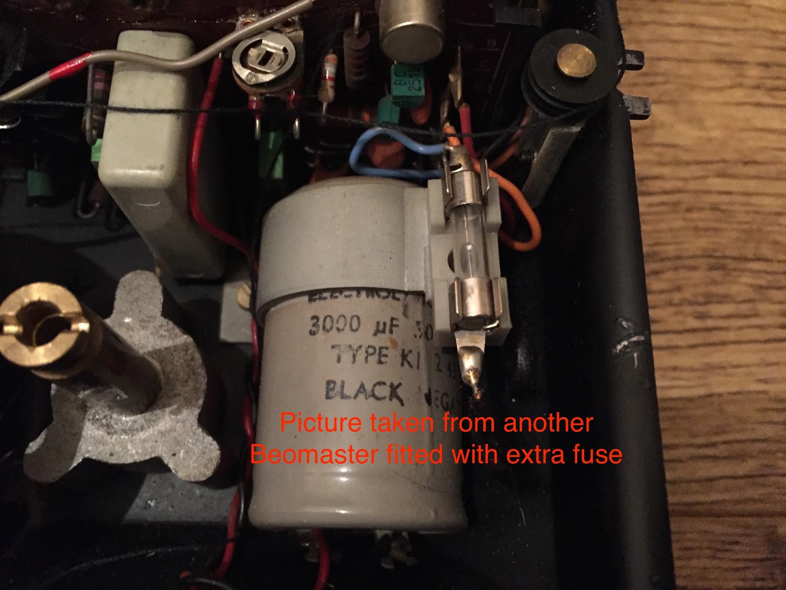
Some Beomaster 6000 quad have an additional fuse of 4A, mounted on top of the bridge holding this 3000 µF capacitor and connected in series with the 27V AC winding. This Beomaster did not have it. It is also not mentioned on any of the electric schematics that I have. I'm thinking of adding this fuse for an extra safety.

The following picture is taken of another Beomaster fitted with this additional fuse. Looking at this picture, it's obvious this was an add-on that was not originally supposed to be there. The B&O engineers must have had some feedback from the service centers after the first series of units were sold........


Time now to connect to the variac and slowly increase the mains supply to see if all is good. Well, hmm, I only got 58,6 V DC out....Should be at more than 60V DC unloaded.


Then I realised that the voltage selector was set on 240V. In the past, my country (Belgium) had 220V on the grid (the UK had 240V), but nowadays Europe is standardised on 230V.  But what I have in my house is more close to 240V (the officially allowed tolerances are +10% and -6%). So, since the voltage selector was set on 240V, I needed to up the variac to  the same 240V. And now I got the required voltage!


With the new trimmers fitted earlier on the power supply PCB, it was now easy the set the stabilised outputs at +18V and -5V.


With this fully operational power supply, I'm now ready to start testing the other boards of this Beomaster.

Sunday, February 11, 2018

Beomaster 6000 (2702) restoration: start of reassembling !

Before starting the reassembling I decided to use a piece of wood to put all the different PCB's, frame's, etc. on. The idea is to test the complete Beomaster while on this wood surface and before mounting it back into the frame. By doing this, you have a bit more space around the different parts that allow checking/fixing before final mounting.

During this "operation" I noted a few things that I wanted to address. The first one was the output stage PCB (#11). This long PCB is placed in a narrow subframe. A very narrow place, packed with wires. The PCB is not really fixed and tends to come out every time you handle it. I wanted a permanent solution to remedy this design flaw.

So I constructed two pieces out of aluminium that were glued on both sides to keep the PCB firmly in place.


They can still be bend slightly whenever the PCB needs to be taken out again.

The second issue was that one of the input DIN5 connectors started to show a possible los of one of the wings (like what happend on the speaker connector). It was replaced with a "new" one.


The piece of wood I used was a 70 x 40 cm OSB type. I had a larger piece laying around in my garage and cut it to measure.

The level and pre-amplifier PCB's where mounted on the output subframe as well.


And now with the SQ decoder fitted as well.


I like to use my iPad Pro to take pictures of everything I dis-assemble and then use the pictures when re-assembling. Off course the service manuals do provide you with all the needed information, but pictures are handy. And it wouldn't be the first time that errors are found in manuals....Or changes that where made during production that never made it back to the drawing boards for modifying the schematics !


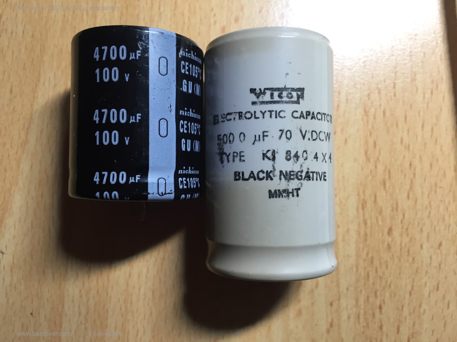
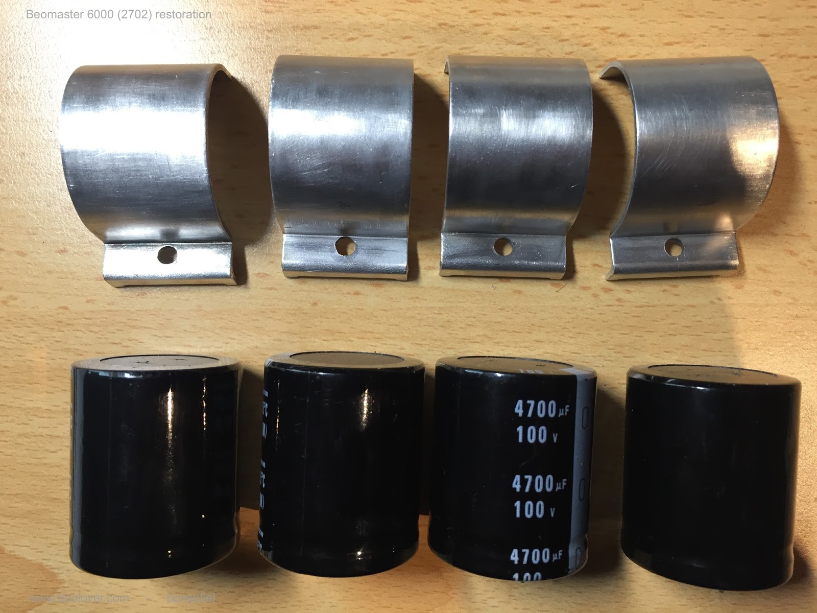
The large output coupling capacitors that are mounted on the black frame with the speaker, input, antenna connectors needed replacement as well. They are fixed with a metal bridge onto this frame. Whenever possible, I like to use new capacitors (in this case Nichicon,  4700µF, 105C type) with the same diameter as the old one. This allows to use the existing metal bridges. Since modern capacitors are smaller than the old one (for the same value), the added advantage is that, keeping the same diameter, they are shorter. This allows for easier connection.


The bridges are off course cleaned and polished first !


And then fitted onto the frame.


It may not look like a Beomaster 6000 quad yet, but it is all starting to come back together !


But still a long way to go...... Keep following my posts !