Featured Post

Beolover SyncDrive: DC Platter Motor Replacement for Beogram 4002 and 4004 (Type 551x and 552x)

Late Beogram 4002 and the 4004 (Types 551x and 552x), which have DC platter motors instead of the earlier synchronous AC motors usually suff...

Showing posts with label no-signal current. Show all posts

Sunday, February 24, 2019

Beomaster 1900 Type 2904: Service manual adjustments and first play

After the indicator lamp replacement I set up the Beomaster 1900 for the no-signal current adjustments of the amplifier.

The adjustment procedure is to measure the voltage across the left and right emitter resistors (R256/R356 respectively) and adjust the left and right trimmers (R249/R349 respectively) so the voltages read 12mVDC.

The emitter resistors are in a bad location to connect up probes from the top of the main board so I connect the measurement probes on the underside (trace side).

There is just enough room to get to the trimmers on the component side for the adjustment.

Here is the left channel


The measurement and adjustment are to be made when the amplifier is cold and first turned on. The volume level should be at its minimum and no speakers should be connected.
Here is the measurement for the left channel emitter resistor
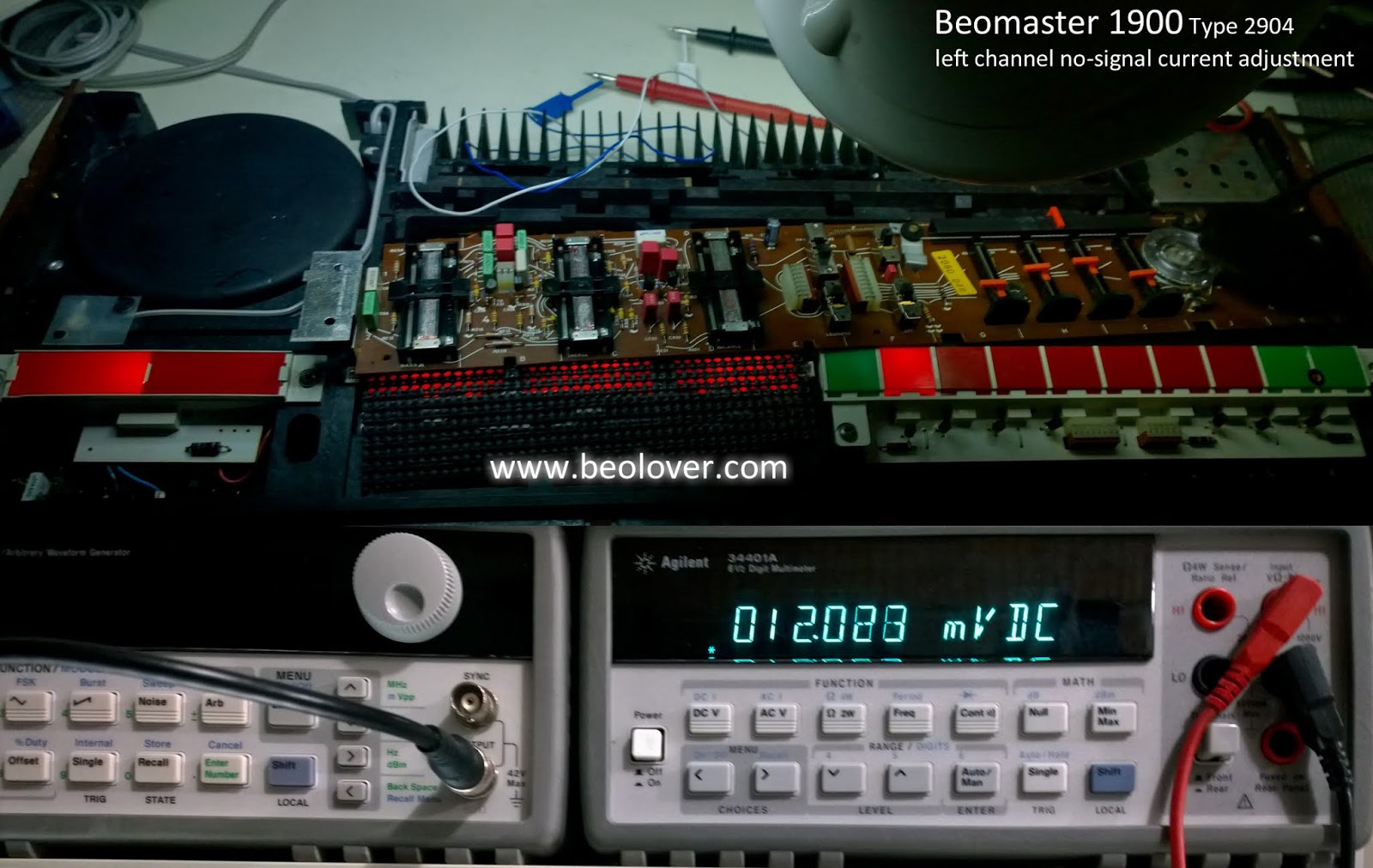


Here is the right channel


Another service manual check and adjustment is for the FM1 tuning voltage.
This test measures across the tuning board 4R1 (4TP1) while setting the Beomaster 1900 to FM1 and the FM1 tuning slider to 88 MHz.  The 4R2 trimmer is adjusted so 4.7 VDC is measured at 4TP1/ground.


The same type of test is performed for FM5. The measurement is again measured across 4TP1 to ground but the FM5 is the selected FM source. The FM5 tuning wheel is turned to 88 MHz then the 4R8 trimmer is adjusted to 4.8 VDC at 4TP1.


Once these adjustments were made I connected up my FM antenna and my workshop Beovox S55 speakers.

This Beomaster 1900 is playing music again and sounding quite nice.


I let the Beomaster play overnight to burn in the new components.  Later today I will start reassembly of the Beomaster then run some performance tests.


Sunday, April 8, 2018

Beomaster 6000 (2702) restoration: checking, power-up and calibration

Everything is back into the chassis and now it's time to do a last check of all the wiring and powering up. It's important to make sure that no wires have been cracked, became loose or touching the chassis. This may seems obvious, but it is so important in a Beomaster 6000 quad because the space is so tight and most wiring is done with hard wires. I took all the time that I needed and found one wire broken off: a ground connection to the pre-amp.

So, a last peek inside before powering up......


I plugged the unit into my Variac transformer, gently raised the voltage to the required 230V and...........it fired up on all engines! I selected a FM station and listened to Katie Melua's version of Louis Armstrongs "What a wonderful world" ! And indeed it was......

That was a big relief. You never know what will happen after such a big restoration. But, off course, I had tested everything already before putting it al in the main chassis (check here). 

Some final calibration was now needed. I started with the power supply. I had done this before when restoring the power supply PCB, but under load settings may change. I found some slight variation. The +18V had now dropped to +17,85. Not to bad. And the -5V was now -5,1V (not sure why it went up). With the new trimmers in place, it was easy to recalibrate to the correct voltages.


On the same power supply PCB, a trimmer is located to balance the FM reception lights.

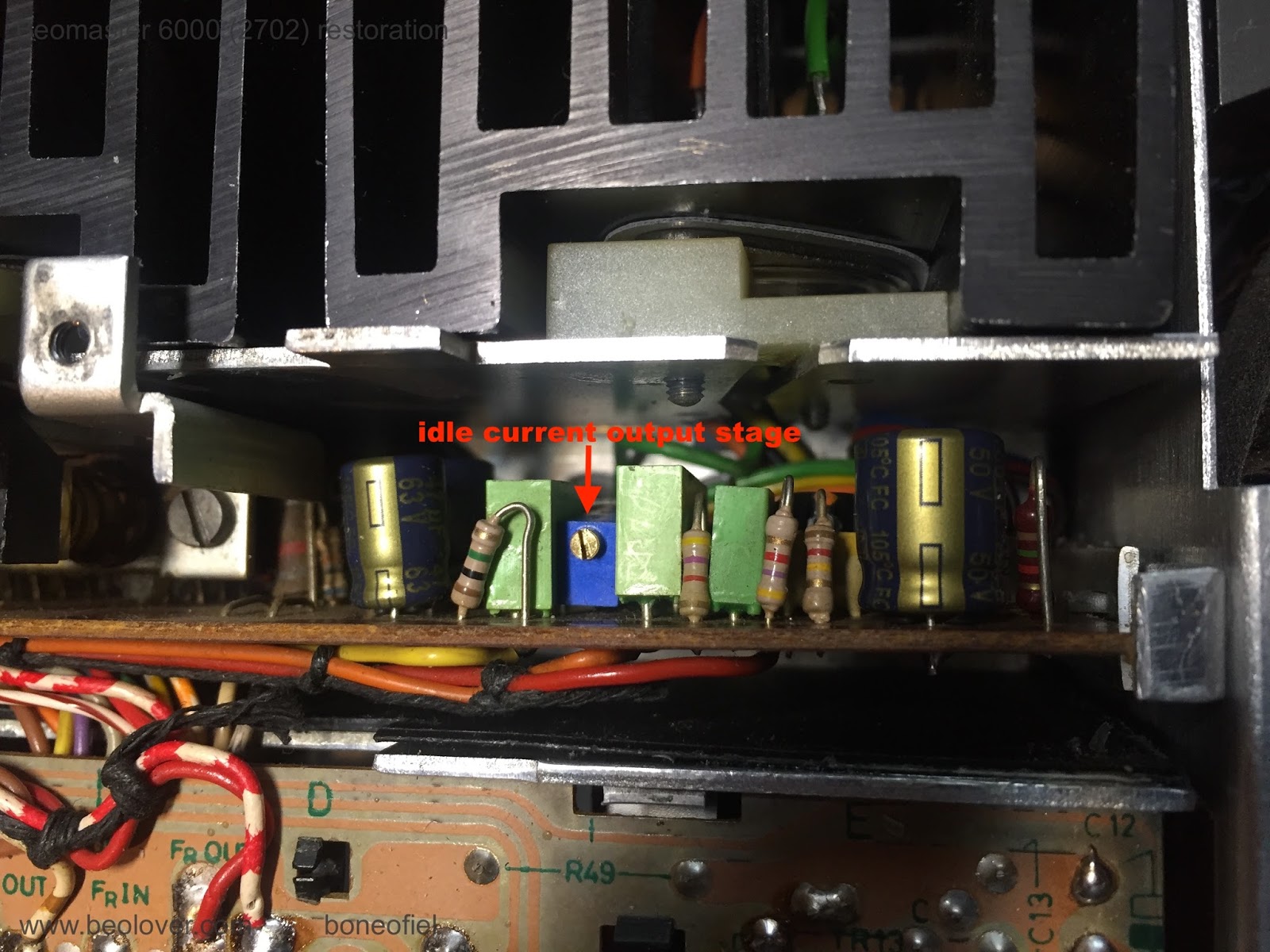
The idle (quiescent, bias or no-signal) current was already set before, but I checked it again by measuring the voltage drop over the 2 emitter transistors (0,12 ohm), in series, that are in each set of the Darlington output stages. The service manual describes to measure directly on one of the collector resistors on the PCB. They are very difficult (if not impossible) to reach once the PCB is in place in the subframe. The easiest way is to measure directly on the emitter contacts of both Darlington transistors (PNP and NPN pair) on the cooling elements (white & green wires in below picture). The correct setting in this case is 14,4mV (2x7,2mV). The extra base-emitter current that flows through the emitter resistors together with the collector-emitter current, is neglectable.


Next was the FM bottom voltage adjustment. The manual describes +4,5V. The FM tuner is driven by a variable DC voltage and to make sure that lowest FM frequency is correct and corresponds with the display, this bottom voltage needs to be set correctly.


Another series of adjustment are related to the FM display board with the signal strength meter, the stereo light and the tuning balance lights.


Other calibrations (like the ultrasonic receiver and the Commander remote) have been done before (see here).

Up next is the mounting of the FM display scale and fixing a new dial cord.

Wednesday, January 24, 2018

Beomaster 8000: Output Amplifier Board Initial Testing

The Beomaster 8000 Output Amplifier boards are recapped and the output transistors have been remounted with new thermal insulators. Before using these amplifier boards they need to be checked out and the no-signal current level adjusted to 18mV across the emitter resistors. I will do a final check again on these once the boards are re-installed in the Beomaster cabinet but while the boards are out it is good to do an initial check.

This check will let me know if there are any serious problems before going to the trouble of re-installing the boards.

For this test outside the Beomaster I need ±55VDC power and +15VDC power to the board. I also need a multi-meter to measure the voltage across the emitter resistors.

I can get ±55VDC with my two 0-60 VDC bench power supplies. These supplies are nice because I can set them up to limit their current to 15mA. That will provide protection against burning anything up should there be a hidden short circuit somewhere (i.e. a bad component).

Here is one of the two identical output amplifier boards ready for the no-signal current adjustment.


Adjusting the no-signal current involves slowly ramping up the ±55V rail voltages simultaneously to 55V. This should result in ±55V ready to go on the positive and negative supply rails. The +15V is then slowly applied to P38-2 which controls current in the output amplifier. The current draw from the  ±55VDC supplies should be around 100mA to 110mA when the output amplifier is on (+15 VDC applied to P38-2). The R226 trimmer resistor adjusts the no-signal current of the amplifier.


My bench multi-meter is more accurate for this adjustment than my hand held DMM so I switched to the bench meter to dial in the 18mV emitter voltage setting.


Here is a picture of the bench power supplies with the output amplifier on and the proper no-signal current level set.


I repeated the adjustment for the other output amplifier board and these two boards are ready to be re-installed in the Beomaster.