Featured Post

Beolover SyncDrive: DC Platter Motor Replacement for Beogram 4002 and 4004 (Type 551x and 552x)

Late Beogram 4002 and the 4004 (Types 551x and 552x), which have DC platter motors instead of the earlier synchronous AC motors usually suff...

Showing posts with label 2017SBBM8000. Show all posts

Monday, March 5, 2018

Beomaster 8000: Wrapping Up Loose Ends & Buttoning Back Up

Over the weekend I finished up a few loose ends on the Beomaster 8000 project and finished the reassembly of this fine receiver.

Because earlier in the project I had found a fault in the rotary encoder sensor assembly for the volume dial I didn't feel comfortable leaving the rotary encoder sensor assembly for the tuner dial in its original state. If the sensor went out in the volume control then the same parts in tuner dial might be due. It is an easy replacement so it is better to do that than risk the sensor failing later.


Loose wiring and bad connectors are one of the biggest problems on the Beomaster 8000. Another common issue is the two ribbon cables that connect to the control keypad board start to come loose over time. That can result in strange behavior. These cables are still working good so I will just add some black hot glue where they are coming loose.

But first the tuner dial rotary encoder sensor update.


I replaced both sensors and the emitter then put the sensor assembly back in place with the re-glued ribbon cables. I also added a dab of hot glue where the small volume and tuner sensor boards attach to the dial. That insures they won't work out of position during shipping.


Earlier in this Beomaster restoration I had to make a mechanical fix of the tone control & filter panel because it had a crack in it. During this reassembly I discovered that one of the mounting screw tabs of that panel was also cracked. Another fix requiring some epoxy.


I had to let the epoxy cure for a few hours but eventually I was able to return to the Beomaster reassembly tasks.

The reattachment of the tone control & filter panel door takes some careful maneuvering to get back in place.


The hard part is done. Next is to add the display cover and heat sink cover.


Then a couple more trim pieces and this Beomaster is finally all back together. It is now ready for some final play testing.


What a nice receiver. I couldn't wait to try it out with its Beogram 8000 I restored earlier so I cleared some space on my largest workbench. A little messy but I was also able to fit in a Beocord 9000 and connect the Beomaster to a pair of S70 speakers. I also have a remote control for the system and it works beautifully.


I will continue this integration test for a couple of days and start preparing the shipping boxes for this Beogram and Beomaster to return to their owner.

Wednesday, February 28, 2018

Beomaster 8000: Evaluating the Audio Performance

This Beomaster 8000 receiver has been playing music in my lab since I finished the recap and output amplifier adjustments. The sound is great as it always is with these receivers but human ears are subjective and we like to measure some key values with test equipment to have some actual numbers to compare with. For amplifiers we typically use a sine wave test input voltage and measure the output of a preamplifier or power amplifier to check the total harmonic distortion (THD) and sound to noise ratio (SNR).

For this Beomaster I set my test up to check some input voltages at some key frequencies and measure the output amplifier at the speaker outputs.

For the speaker output measurement I connected a pair of fixed 8Ω loads. Obviously the fixed resistive load isn't exactly like a real speaker system load but by using the fixed 8Ω load I should always have a good measurement value I can compare other amplifier results to.

Here are my dummy speaker loads. They are power resistors connected to a very large heat sink. When I drive the output amplifier up to its rated power output (100 Watts into and 8Ω load in the case of the Beomaster 8000) the load resistors will get quite warm.


I am going to measure the THD and SNR values with my QuantAsylum QA400 audio analyzer. Since the high speaker output voltages would damage the analyzer inputs I use a low noise differential probe to lower the signal to a level the analyzer will accept.

This picture shows the Beomaster 8000 left and right speaker outputs connect to the dummy 8Ω resistor loads where the differential probe is attached and the signal connected to the QA400 inputs.


For the test inputs I want to use a constant sine wave of 1Vrms at frequencies from 20Hz to 20KHz.
I use the signal generator of an HP8903 audio analyzer for the test input signal and check it with an oscilloscope as I route the test signal to the Beomaster 8000 Tape 1 (TP1) inputs.


I started with a 1KHz signal as that is a common frequency for a lot of the audio specs manufacturers publish. It is also in the middle of the frequency range on the log scale.

It should be noted that before starting the measurements I adjusted the Beomaster 8000 source input levels to set the left and right channel levels as close as possible to each other. Those input level adjustments are on the left side of the Beomaster cabinet.


Using the Beomaster volume control I increased the volume of TP1 while monitoring the output with the QA400 analyzer and the Beomaster clipping lamp.

With the 1Vrms input signal I got to the clipping point when the Beomaster reached 5.9 on the volume indicator. I backed off that volume to 5.8 and measured between 28Vrms and 29Vrms at the speaker load. That corresponds to about 100 Watts of output.

Here is what the QA400 analyzer measured.


The THD levels are very good. Both channels are comfortably less that 0.05%.
For the SNR value I notice that B&O specifies their Beomaster 8000 SNR value as "A Weighted" and should be >77dB for the Tape input. The frequency and output level isn't specified but I am doing my measurements at the maximum rated output level so I turned the A-Weighting on in the QA400 and got these measurements (at 1KHz).


The SNR values are below the expected 77dB for the Beomaster and the left channel THD went up some. It is still below 0.05% but I thought it was odd that it moved and the right channel didn't move much.

Checking other frequencies (400Hz, 10KHz and 15KHz) resulted in the left channel being within THD specs but not as good as the right channel.

These results are not bad but I would like to see closer values for the left and right channels during this testing as I am using the same input signal and the load resistors are identical. A common culprit in the amplifier performance for the Beomaster 8000 are the OpAmps used in the preamplifier board and tone control board. Those are the LF353N, TL072CP and uAF772TC OpAmps. The audio source signals go through these OpAmps so their performance directly affects the Beomaster amplifier performance.

In the case of changing out the OpAmps it is best to change them all (left and right channel). That way all of the signal paths are using new OpAmps that should be pretty much identical.

When replacing the OpAmps I am also going to install 8-pin sockets for the integrated circuits. Here is the preamplifier board with its original OpAmps (seven total)

 Here are the sockets for the new OpAmps.

Here are the new TI LF353N OpAmps installed.


Next is the Tone Control & Filter board. This Beomaster 8000 unit has five OpAmps to be replaced on this board. Note that some Beomaster 8000 units have a six.  This picture shows the five OpAmps replaced.


The OpAmp identified as 4IC6 is for the Beomaster volume control circuit. Whenever that OpAmp is changed it is very likely that the volume control circuit offset adjustment will be necessary to be performed.


Here is the circuit schematic.


The section outlined in red shows the left channel trimmer for the volume control offset adjustment.
You immediately know if the adjustment is necessary because you will hear audible clicks in the related channel's speaker as you turn the volume up or down. Adjusting out the offset removes those click sounds.


Now that the OpAmps are changed out and the volume control offset is readjusted I remeasured the amplifier outputs.

The THD and SNR (A-Weighted) both improved plus the left and right channels are close to the same.


I have done a couple Beomaster 8000 restorations where I replaced the OpAmps with a higher performance TI OPA2134A (SoundPlus) device. However, in measuring the performance with that OpAmp versus a new TI LF343N OpAmp I could not see any measurable differences with the analyzer. Since the OPA2134A costs four times that of a new LF343N I recommend using the latter.

As a final check I used the QA400 impulse stimulus and measurement system to make a frequency response measurement of the Beomaster. This test also uses the same test setup. The difference is the Tape 1 stimulus is from the QA400. I have to admit I am not 100% comfortable with this test yet but it is worth looking at and recording for future reference with other Beomaster unts. The results look pretty good from 20Hz to 15KHz. However, I was hoping the 20KHz level would be a little higher. As it is it measures around -0.8 dB instead of the -0.5dB.


I will finish closing the Beomaster 8000 cabinet back up then do some actual audio component tests using the Beogram 8000 and a Beocord 9000. That will make sure all of the playback and recording features work as well as the Beomaster 8000 remote control.


Tuesday, February 20, 2018

Beomaster 8000: Left Channel Output Amplifier DC Offset Resolved

This Beomaster 8000 is almost fully functional. Actually it does function and play music but it doesn't completely pass the service manual DC Offset adjustment procedure. It is very close but no cigar.

The right channel adjusts perfectly. With the Beomaster on and warmed up I have the right channel output amplifier adjusted so the DC Offset measures 0.0V ± 0.1mV.

The left channel could only be adjusted to around 0.040V (40mV). Here is the differential amplifier circuit where this adjustment is made.


The adjustment trimmer (R200) adjusts the current to even out the differences in hFE between TR201 and TR202 (BC546B NPN transistors). As I said, the left channel cannot be adjusted to the 0.0V ± 5mV range specified by the Beomaster 8000 service manual.


I pulled out TR201 and TR202 to measure them with my transistor tester. Sure enough, their hFE measured quite a bit different. TR201 measures 146 and TR202 measures 318.


I checked a few other BC546B transistors and they are all close to hFE = 300. So TR201 appears to be the culprit. I went ahead and replaced both TR201 and TR202 with BC546B transistors as close of an hFE match as I could find.

That did it. I rechecked the no-load current adjustment first then performed the DC Offset adjustment. Now I can get the left channel output amplifier down to a good DC Offset value.


This Beomaster is feeling like it is into the home stretch now. Time to start closing up the cabinet and doing some real play testing.

Saturday, February 17, 2018

Beomaster 8000: Repaired Rotary Volume Sensor

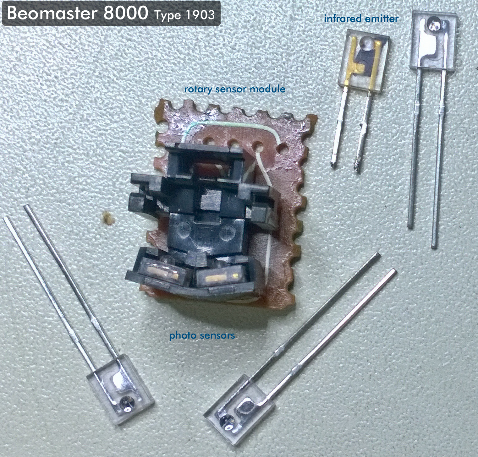
Swapping the volume rotary sensor module on this Beomaster with a spare got the volume control working again. That doesn't mean the original sensor is a throw away and cannot be repaired though. The repair is pretty easy. The sensor module is easy to get to and the infrared emitter and photo sensors can be de-soldered and replaced.

Here is the original, defective rotary sensor module with the replacement parts.


It is difficult tell the emitter device from the sensor just by looking at them. The leads on the emitter are different from photo sensor but to be safe I keep them in their packaging until I am ready to solder them in place.

Just that simple and the original rotary sensor is working in the Beomaster again. My spare sensor assembly can go back in my spare parts bin.


Now for that pesky left channel DC offset problem.

Wednesday, February 14, 2018

Beomaster 8000: Power Testing the Receiver

Time to catch up with the status of the Beomaster 8000 restoration. I left off with the Beomaster reassembled and ready for its initial power up test.

Plugging the Beomaster into the AC power outlet for the first time is always filled with a little nervous excitement but it was all anticlimactic. Nothing visually happened. Mainly there was no red dot on the display board showing that the Beomaster was in standby mode. As I unplugged the Beomaster I did hear one of the power relays click so that was good to hear.

When this sort of thing happens the first thing to investigate is what is going on with the power supply. The 120 VAC, 60 Hz line voltage was there at the transformer (my house is actually 125 VAC). The 5 VDC regulator was measuring 5 volts. The ±15 VDC regulators and the ±55 VDC rail voltages were not present...but that is to be expected on initial start up if the unit never gets past the standby mode.

I opened the lid to the processor board and verified +5 VDC to the processor chips. That wasn't so welcoming of news. It means a problem on the microcomputer board.

I have three spare Beomaster 8000 microcomputer boards for this type of scenario. I swapped in the first one and tried power on the receiver again.

This time the standby LED illuminated.


Now I could start exercising some Beomaster 8000 operations. A recheck of the voltages showed me the ±15 VDC on the +15 and -15 voltage regulators. The large reservoir capacitors for the 55 VDC rails measure ±56 VDC.


During those above tests I also tried to increase the volume level but it was stuck on zero.
The problem with that could be anything from the rotary volume wheel sensor (or cable) and the microcomputer IC.

I tried a second spare microcomputer board with the same result so the problem is most likely the sensor or sensor cable. I have a spare sensor to swap with so I tried it.


There it is. The original rotary volume wheel sensor assembly has a problem. The replacement sensor assembly allows the microcomputer board to adjust the volume level up and down.


That left me with some decisions to make regarding this Beomaster microcomputer board. I have spare boards ready to go but I also have one set of Beomaster 8000 master and slave processor chips. The set is used and I don't know 100% if they are good but I decided I might as well exhaust all of the options I have. I installed the spare processor ICs in the original microcomputer board I took out of this Beomaster and gave it a try.

What do you know, the replacement processors bring the Beomaster into standby mode and then to on mode. The volume control works but now there are missing segments from the display. I know the display board itself is fine as I ran a 24 hour burn-in test on those display modules earlier.  So is the segment problem due to the processor chips or are there additional problems on this microcomputer board?


I decided to reflow the solder joints of the signal paths for the display segment drivers along with trying a couple replacement driver ICs (SN74247) I have for IC1 and IC2. The results were not successful and the problem got worse.


Eventually I got to a point where the microcomputer board would not function again. Not totally surprising as I wasn't confident that the replacement ICs I have available for testing this microcomputer board were good so I decided to go ahead and use one of my spare, working microcomputer boards as a replacement for this project. It is the safest and more reliable direction to go. I considered moving parts from the spare board to the original board out of this Beomaster but that would be an unwise risk. The less handling of the processor chips the better (even with wearing anti-static straps).

Spare board installed...These are much better results.


Moving on I found another problem with the Beomaster.  After the original bench testing of the output amplifier boards where I set the initial no-load idle current, I rechecked the left and right output amplifiers again now that they are re-installed.

The idle current check still measures good so I moved on to the DC offset voltage adjustments (for the left and right channels).  The right channel easily adjusted to the specificied tolerances of the service manual : 0.0 ± 5mVDC.  I am at 0.0 - 0.6mVDC on the right channel.


On the left channel adjustment I can only adjust the DC offset down to around 0.0 ± 50mVDC.


It isn't a high enough value to prevent me from test playing the Beomaster. I have been playing the radio and an ipod connected to TP2 for a few hours now.  However, it is not satisfactory to leave it like this. I will have to pull out the left channel output board and investigate the problem with the offset.