Featured Post

Beolover SyncDrive: DC Platter Motor Replacement for Beogram 4002 and 4004 (Type 551x and 552x)

Late Beogram 4002 and the 4004 (Types 551x and 552x), which have DC platter motors instead of the earlier synchronous AC motors usually suff...

Showing posts with label performance testing. Show all posts

Saturday, March 20, 2021

A Pair of Beomaster 1900 Receivers for Restoration: Unit #2 Performance Testing and a Volume Control LDR Problem

Today I finished some of the Beomaster 1900 service manual adjustments and began looking at its performance with THD (total harmonic distortion) and Frequency Response.

First a couple of service manual adjustments to make.
The Beomaster 1900 service manual calls for adjusting the tuning voltage for FM 1 and FM 5.
Specifically, the FM 1 tuning potentiometer (4R3) is to be set on the 88MHz dial position. 
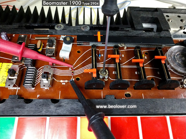
With FM 1 selected as the Beomaster 1900 music source the 4R2 trimmer is adjusted so test point 4TP1 measures 4.5 VDC. 

Similarily, the FM 5 tuning potentiometer (4R7) is set to 88MHz.  With FM 5 as the selected music source trimmer 4R8 is adjusted to get 4.6 VDC ... also at test point 4TP1.

Here are those measurement and adjustment points.


The last service manual adjustment I made was to adjust the output level trimmer 2R136.
For this adjustment an input signal of 200mVrms, 1KHz (sine wave) is applied to the Beomaster 1900 Tape input. With the Beomaster 1900 volume preset on the middle setting the Beomaster is turned on by selecting the Tape source button. At that volume level the output of the Beomaster (as measured at the speaker outputs) should be at 100mV.  Trimmer 2R136 is used to adjust that level.

I set the test up by configuring a 200mVrms, 1KHz test signal out of the QuantAsylum QA401 Audio Analyzer.  I verified the signal with an oscilloscope then applied it to the Beomaster 1900 tape inputs.
I set the volume preset to the middle button and selected the Tape source button to turn the Beomaster 1900 on.  Then I measured the voltage at speaker loads.

Here is the test setup and the measurement results.


The left and right channels differ in output by 20mVrms. That isn't horrible but I expect them to be closer.

The Balance control was correctly in the center. The no-load current adjustments are almost identical.
I guessed that the problem must be in the Beomaster 1900 volume control LDR device.
That is a light controlled resistor device that uses a lamp whose intensity changes via electronic control. The amount of light then changes the resistance values of a set of photo resistors to control the Beomaster 1900 volume levels.

Just to investigate a little further I went ahead and checked the Beomaster 1900 THD (total harmonic distortion) at 30Watts (with 8 ohm dummy speaker loads). 


The THD values are good but the left channel is at about 20 Watts while the right channel is at about 30 Watts.

I needed to investigate the volume control LDR device.

Here are some photos of it.


Here is a photo of the volume control LDR device disassembled.
A single lamp in the center of the device emits light to four LDR devices.
When there is no light the resistance level of the LDR is at its highest and corresponds to full volume of the Beomaster 1900 amplifier.
As the lamp begins to emit light the LDR resistance decreases and attenuates the audio signal.


The photo shows four LDR devices around the lamp in the volume control device.
Two LDR devices are for the left channel and two are for the right channel.
One set (L & R) are for voltage levels in the tone control circuit and the other set (L & R) are for the voltage level in the output amplifier.

To test this device out I connected the two wires for the lamp to a DC power supply and set the voltage to 5 VDC.  Then I measured the resistance of each of the four resistors to see how close in value they were to each other. 

I discovered that the four LDR devices in the volume control of this Beomaster 1900 unit did not have a consistent resistance value for my test voltage.

I measured several LDR devices with my test setup and selected four LDR devices that were very close to each other in value. 

I reinstalled those into the volume control casing and then back into the Beomaster 1900.
Then I repeated the Tape input level adjustment.

This time the difference in the left and right channel is about 7mVrms.  That is much better than the previous 20mVrms difference.


What about the left and right channels at maximum power output?

The Beomaster 1900 spec sheet says the maximum power output of the Beomaster 1900 amplifier is rated at 2 x 20 W/8 ohms. The maximum total harmonic distortion is listed as less than 0.2%.
Due to the nature of the touch sensitive volume control it is difficult to dial in a precise volume level for this check.  I ended up with measurements at output levels of 15W, 28W and 32W.

All three measured well below the target 0.2% THD value.

Here is the THD measurement at 28 Watts across my dummy 8.1 Ohm speaker loads.


Those are nice distortion percentages and at a higher output level than the specification sheet.
Also notice that the left and right channel output levels are much closer to each other than before I worked on the volume control LDR device.  I am satisfied with these results.

The last test is a frequency response test. I set the voltage level to output 26W of output from the Beomaster 1900 amplifier across the 8.1Ohm dummy speaker loads. 
Here are the measurements from my QA401 Audio Analyzer.


That measurement is right in line with what I have been seeing on the Beomaster 1900 and 2400 amplifiers. The frequency response is comfortably between ±1.5dBV from 20Hz to 20KHz.  This Beomaster 1900 is actually performing at ±1dBV through that frequency range. Plus that is above the expected maximum output level. 

I will continue on with the reassembly of the Beomaster cabinet parts then put the unit into listening testing.

While I am doing that I will begin a couple of fun Beogram turntable restorations and a change of belts on a Beogram CD50 unit.


Monday, September 9, 2019

Beomaster 2400 Type 2902: Retesting performance measurements after the right channel rework

My break from the workbench is over. Time to resume and wrap up this Beomaster 2400 restoration.

I left off with the discovery that the right channel output amplifier was distorting.

In resuming work on this Beomaster I removed and tested all of the right channel output amplifier transistors out of circuit. It wasn't any surprise that they all tested good since the right channel was working at low power levels. That being the case I decided to replace all of those transistors in the right channel along with the two emitter resistors. I also wasn't happy with the single-turn trimmer resistors I had installed for the no-load current adjustment. The single-turn resistors are fine but I prefer a multi-turn resistor for that particular adjustment. It is easier for me to dial in the correct value and feels more precise.
Here are pictures of the transistors that were replaced and the new trimmers.


The new multi-turn trimmers made re-adjusting the no-load current adjustment a breeze.

Now it was time for checking the left and right output amplifier channels THD again.
This type of measurement poses a problem regarding my stating that the THD for this amplifier is exactly per the service manual published technical data.

For one thing, the published audio specs stated by various manufacturers are a little vague. They often quote DIN specs that they followed but details of those specifications are difficult to find. Even then, the measurement equipment is different now.

My methodology is to use the manufacturer specs as a guide but measure all of my amplifiers using my own same test setup and same measurement devices. That gives me a set of data I know the source of and can use for comparison.

I have shown this before but here is my test setup.

I use a fixed, dummy speaker load of 8.08Ω on each channel. The 0.08Ω part of the load is a series sense resistor that I can connect my audio analyzer probes to for making power signal measurements with. The audio analyzers have limits on the AC voltage they can handle. While my QuantAsylum QA401 analyzer does have built in attenuators I still need to be careful.


The test connections go to my signal generator, QA401 analyzer, multimeters, oscilloscope, dummy load restistors and the amplifier under test (BM2400 in this case).

I use the multimeters to verify the AC signal the amplifier is outputting to the load resistors.
The Beomaster 2400 doesn't have a volume control that you can tell the precise volume level you are on. It does have three preset volume levels you can select from on start up though so I usually use those.  Then I use the amplitude adjustment of the test signal generator and check the amplifier output with the multimeter to dial in a precise measurment output. The oscilloscope also aids in monitoring the actual input signal and amplifier output signal.
The QA401 audio analyzer measures the THD.


Here is a quick look at the Beomaster 2400 service manual technical data.


I am only interested in the rated power output and the distortion data.
Bang & Olufsen states here that they used DIN 45 500 for their measurement specification. I don't have those specs and I'm not sure they would really help me with the test equipment I have on hand.

So I will use the technical data that says this amplifier should be able to output 20W into 8Ω speaker loads. It should do that at a THD value close to what the THD is at lower output power.  My dummy loads are fixed resistor loads and that is fine as I use those on all of my tests. Plus I am collecting my own measurement data for apple to apple comparisons.

The service manual stated harmonic distortion spec of 1000Hz, 50mW : <0.07% seems kind of odd.
I am reading that to mean a 1000Hz test sine wave input and the Beomaster output set to only 50mW  across an 8Ω load. That is only about 0.6Vrms.

I decided to go ahead and make that measurement anyway but I still will do my own THD measurement at the full 20W output.

Here is the 50mW THD measurement for the left and right channels of the Beomaster 2400.


Both channels are in the 0.035% range which is well below 0.07%.
So if that is what the published spec meant then great.

For my own full power test at 20W of amplifier output across the 8Ω loads I get this -


This is what I wanted to see. The left and right channels are both performing close to each other and at a respectable THD of around 0.04% (at full rated power).
The Beomaster 2400 heatsinks do really warm up at this output level and normal listening level for the amplifier is probably down around 1W to 5W.

One last note about just doing the THD measurements here. Most of the time restorers rely on listening to known, good music sources through known good speakers to check the result of an audio restoration.  That is fine and an important test to pass.  I just feel more comfortable in having a repeatable instrument measurement test as a means to check that there isn't something hidden going on and that both channels measure close to what my other restorations have been. It paid off in this case because this Beomaster sounded fine in my initial listening tests after the recap but the higher power testing revealed a problem.

This amplifier is ready to move on to the final functional tests.
Those are where I will connect up a Beogram and Beocord then play the Beomaster 2400 for several days continuously (most of the time using FM as the source).

Saturday, July 20, 2019

Beomaster 2400 Type 2902: Problems found during performance testing

This Beomaster 2400 had breezed through the early burn-in tests and listening to it during that time sounded like any other restored Beomaster 1900/2400 amplifier. To really compare the performance however we like to take some THD (total harmonic distortion) tests and look at a frequency response plot.

The early THD tests showed nice values at close to 6 Watts of output into 8Ω dummy speaker loads.


As I continued measuring the performance while increasing power the output began to deteriorate to where I was getting out of spec THD prior to reaching the rated 20W power output. Actually, my Beomaster 2400 Type 2902 claims 25W continuous power into an 8Ω load. The Type 2901 service manual claims 20W continuous power into an 8Ω load.

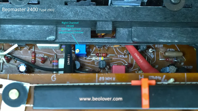
I stopped and rechecked the no-load current settings.


Those values look good so I did another physical check.


I could see some cracks in the emitter resistors. Pulling them out and measuring them didn't reveal any problem with their value though but I changed them anyway. Because the Beomaster still plays decently this is a case where it would be helpful for a hard over failure.  As it is I will have to start replacing and retesting parts in this Beomaster output amplifier. Pulling out transistors and measuring them while they are not under load will likely not reveal a bad transistor.

This will take a bit of time and I already scheduled a week or two off so I will pick this amplifier back up later.

Monday, August 6, 2018

Beomaster 4400 (2419): 30 Hour 60dB Test

Functional testing update...
Because of the earlier incident with the left channel 5R173 and 5R174 resistor failures I am putting this Beomaster through extra long burn-in testing.

Over the weekend this receiver successfully played continuously for thirty hours at a volume level that produced 60dB to 65dB of sound out of my Beovox S55 speakers (measured from 15 feet away).
The output transistors on the heat sinks measured around 100°F to 120°F at various times during the thirty hour test.


The testing continues.

Wednesday, August 1, 2018

Beomaster 4400 (2419): Amplifier Frequency Response Check Plus A Fault Detour

In the last post I showed the results of some THD tests with the Beomaster 4400.  I used a 1KHz, 2Vp-p sine wave input signal at Tape 1 and Tape 2. Then I used the QuantAsylum QA400 analyzer to measure and display the output signal across 8Ω dummy speaker loads.  I also ran the volume of the Beomaster up to its maximum output right before the overload lamp illuminates. The Beomaster passed those performance tests really well.

After letting the Beomaster sit for a couple of days while I took care of some other things I powered it back up for some frequency response testing.  To my horror and surprise the left channel output amplifier had smoke!  I quickly unplugged the Beomaster and examined the damage. The smoke came from the main board 5R173 and 5R174 resistors.  They are 68Ω 1/8W metal film resistors and completely failed where they were open circuit now. Surprisingly there was not burnt areas of the circuit board and no other components appeared to be damaged. Quite puzzling considering the Beomaster had just come off almost 30 hours of testing.  Twenty-four hours of that was continuous playing of music on the Beovox S-55 speakers.

The next step was to try and figure out if there were other damaged components and how many.

Here is the related circuit. It is the left channel output amplifier circuit and shows that the two 68Ω resistors connect to the -35VDC rail. They get current when 5TR119 turns on. Too much current had to of gone through both R173 and R174 to cause them to burn up.


Here are the two burned resistors.


Here is the PC5 board - fault area. The photo shows the D103 12V zener removed for testing.


I removed related components to R173 and R174 as well as some other components that were in close proximity to test if anything else was damaged.

The D103 12V zener diode was a suspect because it controls TR119 which must of allowed too much current down through the two 68Ω, 1/8W resistors.

D103 was placed on a breadboard with a 1KΩ resistor to check if the zener still works. Using a bench power supply I applied 30VDC across D103 and the load resistor.  The zener held at around 12.5VDC.  I tried this several times and D103 appeared to be fine.

I couldn't find any components that tested faulty so I re-installed everything I removed.


Next I used my variac to slowly apply AC power to the Beomaster while watching R173 and R174.  I reached 120VAC on the variac without incident.

At this point I have to figure there was some problem on the board. Most likely a bad solder joint. Uninstalling and reinstalling the components around the fault area forced a re-flow of the solder joints.

I powered the Beomaster off and on several times and it appeared to be back to normal.

A little history on this Beomaster unit...
The owner told me when I started on the restoration that he had smelled burning in the receiver before but that it went away. After a period of time though, there was a loud squawk in one of the channels and the Beomaster stopped functioning. The Beomaster was taken out of service and eventually sent to me.

When I opened the Beomaster for restoration one of the inspections I did was to look for burnt components. I didn't find any. I thought the recapping work took care of any bad component behavior and solder joint problems. Then this fault occurred...even after the lengthy initial burn-in testing.

So I still worry there might be a weak component that is really the culprit. That means I will have to put this Beomaster through a much longer burn-in test period once I wrap up the frequency response and functional tests.

Continuing on with the frequency response measurements....
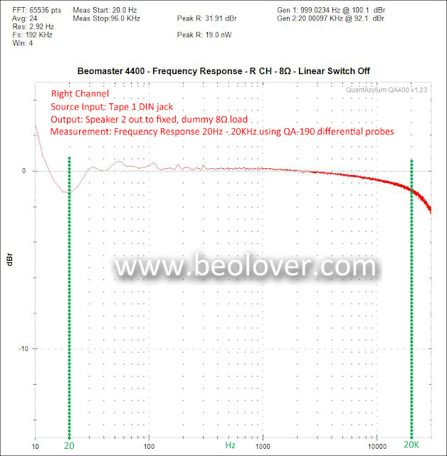
Like the 1KHz THD tests I used the Beomaster tape inputs to apply the QA400 frequency response impulse stimulus. The QA400 inputs were connected to the 8Ω dummy speaker loads through a QA190 differential voltage probe. The frequency response measurement function of the QA400 was then used to measure the response curve.

My initial frequency response measurements were okay, not great. Even with the differential probe measuring one channel at a time I get some noise that makes taking the measurements I would like a little difficult.

Here are the first set of frequency response curves I measured.


Both channels roll off a little steeper than I would like and the right channel is not flat at all.

The Beomaster 4400 Linear switch allows you to bypass the tone control circuit so I tried the measurements with the switch engaged.


That is a definite improvement versus going through the tone control circuit.
I cleaned the bass, treble and balance slider pots as well as the high and low filter switches to see if that helped the tone control path.


It looks like the right channel improved with a flat curve between 100Hz and 3KHz now.  My probe isn't doing a good job below 100Hz however so I am not able to get an accurate assessment of that part of the response.

Soundwise this Beomaster sounds good to me so I will keep these measurements filed as a reference for the next Beomaster 4400 units I have in my backlog.

The next steps for this Beomaster are to check out the phono input and the tape record paths of Tape 1 and Tape 2.  Once those have been tested I will hook this Beomaster to some audio components in a listening room for an extended burn-in test. If the R173 and R174 over current problem is still there it should expose itself during that period.

Thursday, May 24, 2018

Beomaster 8000: Wrapping Up The Performance Tests

The current Beomaster 8000 restoration project has been going through quite a bit of testing in the last few weeks. Its owner mentioned that this Beomaster would occasionally come on by itself. Sometimes in the middle of the night it would come out of Standby mode and start playing music. It's always nice to listen to a Beomaster 8000 but you do want it to obey your commands.

I was confident that the restoration work I performed would address that issue but to test it I left the Beomaster plugged in on Standby mode for three full days. No hiccups and it never went into play mode by itself.

It was back to more listening tests while I set up the bench for some performance tests.

As Beolover recently posted, we don't really have the specific test information and test equipment that Bang & Olufsen used when they tested these Beomaster 8000 amplifiers with respect to what is in their technical specifications. On amplifiers there are usually only two service manual adjustments. No-load current (idle current) and DC Offset. That is the case with the Beomaster 8000. Other than those two adjustments a restored amplifier is expected to perform at the manufacturer listed specs for their design. We can use their published specifications as a guide as we collect our own measurements using test equipment available to us today. With these new measurements we will have measurable and repeatable values to compare our amplifier restorations.

Both Beolover and I use the QuantAsylum QA400 Audio Analyzer to make measurements. We also both use 8Ω fixed loads (power resistors mounted to large heatsinks) as dummy speaker loads during the tests. A small 0.08Ω to 0.1Ω resistor is added in series on each speaker load to allow direct measurements to the QA400 analyzer.  That is because the full voltage across the 8Ω load would damage the analyzer inputs. I have a pair of  QuantAsylum QA190 low noise, differential probes that allow measuring directly across the 8Ω (actually 8.08Ω in my case) dummy load. It should be noted that the updated QuantAsylum QA401 analyzer has built in differential inputs so the external probes are no longer necessary.

Here are some pictures of my test setup.


To run a direct measurement to the QA400 analyzer inputs from the 0.08Ω series resistor I use a coax cable with BNC connections for the analyzer and mini-grabbers for the 0.08Ω resistor.


Here is the Beomaster under test with the QA400 analyzer in the background and its measurement screen on my lab computer.


The QA400 analyzer, as described in Beolover's post, outputs a tone burst test signal for single frequency stimulus tests and a square wave impulse for frequency response test stimulus. I can run both left and right channel measurements at the same time as the analyzer provides the input to the Beomaster Tape 1 or Tape 2 left & right channel source inputs.

This test setup is easy to use and I can connect a bench DMM to the speaker loads to measure the actual voltage put out by the Beomaster output amplifier. One problem I run into is occasional noise that mucks with the measurement device sometimes. Usually down at the line 60Hz frequency. In my test setup the direct measurements across my 0.08Ω series resistor just don't provide as clean a measurement as the QA190 differential probes. I also have to monitor the QA190 probes though as they are battery powered (so the batteries need to be fresh).

For these Beomaster 8000 performance tests I decided to first grab a THD measurement for a 1KHz input signal right before it goes to the Beomaster Output Amplifier board. The audio signal goes from the input source (Tape 1 or 2) through the Preamplifier then to the Filter & Tone Control board. The path from the Filter & Tone Control board to the Output Amplifier is via connector 4P24. For this low voltage test I did use some direct probes with alligator clips to the QA400 inputs and not the QA190 probes. That is because of the space available to connect probes to.

Here is the THD measurement for a 1KHz input signal at 4P24.


The left and right channel THD is very low after going through all of the preamplifier and tone control circuitry.  Though it is very low (nearly -100dB) you can see the effect of some 60Hz noise picked up by the measurement cable.

Next was the 1KHz signal THD measurement after the Output Amplifier. This is measured across the 8.08Ω fixed speaker load at different output levels. It should be noted that during these tests I took the opportunity to calibrate the Tape 1 and Tape 2 input level trimmers again so I could make sure they are equal. I also tried to set them where I could set the Beomaster volume control on a level that produces 100W across the 8.08Ω load.  The result of that is a Beomaster volume level of 5.4 producing my 100W test output. The next volume level up (5.5) with this setup causes the clipping light to illuminate.

Here are left and right channel THD and SNR measurements at volume levels of 5.4 (~100W) and 5.3 (~67W).  I also turned the analyzer A Weighting mode on as the B&O specs use that.


The next volume level up (5.5) on the Beomaster puts the output amplifier into clipping so THD of 0.01% at the rated maximum power into 8.08Ω is very good. The next volume setting down (5.3) drops the THD to 0.008%.

Next is a check of the Beomaster frequency response. Beolover also describes this measurement with the QA400. I am showing the measurement picture produced by the QA400 measurement software (with a few of my own text comments added). It has frequency markers for three points I wanted to focus on (1KHz, 10KHz and 20KHz).


My results are pretty similar to what Beolover got although it appears the QA190 differential probes helped my measurements out on the low frequency noise. The drop at 20KHz was right around 1dB which is more than what the B&O published specs state but then our measurement methods are not exactly the same. Between these Beomaster performance results and the last few we have done it compares with very similar results. The results are definitely a pass for this Beomaster receiver.


Wednesday, February 28, 2018

Beomaster 8000: Evaluating the Audio Performance

This Beomaster 8000 receiver has been playing music in my lab since I finished the recap and output amplifier adjustments. The sound is great as it always is with these receivers but human ears are subjective and we like to measure some key values with test equipment to have some actual numbers to compare with. For amplifiers we typically use a sine wave test input voltage and measure the output of a preamplifier or power amplifier to check the total harmonic distortion (THD) and sound to noise ratio (SNR).

For this Beomaster I set my test up to check some input voltages at some key frequencies and measure the output amplifier at the speaker outputs.

For the speaker output measurement I connected a pair of fixed 8Ω loads. Obviously the fixed resistive load isn't exactly like a real speaker system load but by using the fixed 8Ω load I should always have a good measurement value I can compare other amplifier results to.

Here are my dummy speaker loads. They are power resistors connected to a very large heat sink. When I drive the output amplifier up to its rated power output (100 Watts into and 8Ω load in the case of the Beomaster 8000) the load resistors will get quite warm.


I am going to measure the THD and SNR values with my QuantAsylum QA400 audio analyzer. Since the high speaker output voltages would damage the analyzer inputs I use a low noise differential probe to lower the signal to a level the analyzer will accept.

This picture shows the Beomaster 8000 left and right speaker outputs connect to the dummy 8Ω resistor loads where the differential probe is attached and the signal connected to the QA400 inputs.


For the test inputs I want to use a constant sine wave of 1Vrms at frequencies from 20Hz to 20KHz.
I use the signal generator of an HP8903 audio analyzer for the test input signal and check it with an oscilloscope as I route the test signal to the Beomaster 8000 Tape 1 (TP1) inputs.


I started with a 1KHz signal as that is a common frequency for a lot of the audio specs manufacturers publish. It is also in the middle of the frequency range on the log scale.

It should be noted that before starting the measurements I adjusted the Beomaster 8000 source input levels to set the left and right channel levels as close as possible to each other. Those input level adjustments are on the left side of the Beomaster cabinet.


Using the Beomaster volume control I increased the volume of TP1 while monitoring the output with the QA400 analyzer and the Beomaster clipping lamp.

With the 1Vrms input signal I got to the clipping point when the Beomaster reached 5.9 on the volume indicator. I backed off that volume to 5.8 and measured between 28Vrms and 29Vrms at the speaker load. That corresponds to about 100 Watts of output.

Here is what the QA400 analyzer measured.


The THD levels are very good. Both channels are comfortably less that 0.05%.
For the SNR value I notice that B&O specifies their Beomaster 8000 SNR value as "A Weighted" and should be >77dB for the Tape input. The frequency and output level isn't specified but I am doing my measurements at the maximum rated output level so I turned the A-Weighting on in the QA400 and got these measurements (at 1KHz).


The SNR values are below the expected 77dB for the Beomaster and the left channel THD went up some. It is still below 0.05% but I thought it was odd that it moved and the right channel didn't move much.

Checking other frequencies (400Hz, 10KHz and 15KHz) resulted in the left channel being within THD specs but not as good as the right channel.

These results are not bad but I would like to see closer values for the left and right channels during this testing as I am using the same input signal and the load resistors are identical. A common culprit in the amplifier performance for the Beomaster 8000 are the OpAmps used in the preamplifier board and tone control board. Those are the LF353N, TL072CP and uAF772TC OpAmps. The audio source signals go through these OpAmps so their performance directly affects the Beomaster amplifier performance.

In the case of changing out the OpAmps it is best to change them all (left and right channel). That way all of the signal paths are using new OpAmps that should be pretty much identical.

When replacing the OpAmps I am also going to install 8-pin sockets for the integrated circuits. Here is the preamplifier board with its original OpAmps (seven total)

 Here are the sockets for the new OpAmps.

Here are the new TI LF353N OpAmps installed.


Next is the Tone Control & Filter board. This Beomaster 8000 unit has five OpAmps to be replaced on this board. Note that some Beomaster 8000 units have a six.  This picture shows the five OpAmps replaced.


The OpAmp identified as 4IC6 is for the Beomaster volume control circuit. Whenever that OpAmp is changed it is very likely that the volume control circuit offset adjustment will be necessary to be performed.


Here is the circuit schematic.


The section outlined in red shows the left channel trimmer for the volume control offset adjustment.
You immediately know if the adjustment is necessary because you will hear audible clicks in the related channel's speaker as you turn the volume up or down. Adjusting out the offset removes those click sounds.


Now that the OpAmps are changed out and the volume control offset is readjusted I remeasured the amplifier outputs.

The THD and SNR (A-Weighted) both improved plus the left and right channels are close to the same.


I have done a couple Beomaster 8000 restorations where I replaced the OpAmps with a higher performance TI OPA2134A (SoundPlus) device. However, in measuring the performance with that OpAmp versus a new TI LF343N OpAmp I could not see any measurable differences with the analyzer. Since the OPA2134A costs four times that of a new LF343N I recommend using the latter.

As a final check I used the QA400 impulse stimulus and measurement system to make a frequency response measurement of the Beomaster. This test also uses the same test setup. The difference is the Tape 1 stimulus is from the QA400. I have to admit I am not 100% comfortable with this test yet but it is worth looking at and recording for future reference with other Beomaster unts. The results look pretty good from 20Hz to 15KHz. However, I was hoping the 20KHz level would be a little higher. As it is it measures around -0.8 dB instead of the -0.5dB.


I will finish closing the Beomaster 8000 cabinet back up then do some actual audio component tests using the Beogram 8000 and a Beocord 9000. That will make sure all of the playback and recording features work as well as the Beomaster 8000 remote control.